
|
| |
|
Строительный блокнот Introduction to electronics energy. The defining equalitms [)IThe LFR are: mm Pin (1B.5) (18.6} (18.7) When the LFR ouipul pon is connected to a resistive load of value R. the dc output rms voltages and currents V j and iue related to the ac input rms voltages andciirrents ,mj and lac.rms follows: (18.8) (18,9) The properties of the power source and loss-tree resistor network are discussed in Chapter 11. Regardless of the specific converterimplementatlon, any single-phase rectifier having near-ideal properties can be modeled tising the LFR two-port model. 18.2 REALIZATION OF A NEAR-IDEAL RECTIFIER Feedback can be employed to cause a converter that exhibits controlled dc transformer characteristics to obey the LFR equations. In the single-phase case, the simplest and least expensive approach employs a full-wave diode rectifier network, cascaded by a dc-dc converter, as in Fig. 18.3. The dc-dc converter is represented by an ideal dc transformer, as discussed in Chapter 3. A control network vturies the duty cycle, as necessary to cause the converter input current i(t) to be proportional to the applied input volt- dc-dc convener 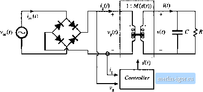 Fig. 18.3 Synthesis of an ideal rectifier hy varying the duty cycle of a PWM dc-dc converter, age v,() as 111 Eq. (1S. 1). The effective tums ratio t>f the Ideal transformer then varies with time. Ideal waveforms are illustrated in Fig. iK.4. If the applied inpul voltage vO is sinusoidal. vJj) = Vy, sin (tut) llien tlie reclilled voltage is v (/) = V sin (Ы1)\ (ts.io) vW (is.ii) It is desired thtil the converter outpul voltage be a constant dc value !(/) = V. The converler conversion ratio /дДО must therefore be Af(rf(0) = v(0 V VfU) U I sin (01/) I (18.12) This expression neglects the converter dynamics. As can be seen from Fig. 18.4, the conlroller must cause the conversion ratio to vary between infinity (at the ac line voltage zero crossings) and some minimum value M; (al llie peaks of the ac line voltage waveform). A, ( is given by .....-t (Ш.П) Any ctmverler Itjptdogy whose ideal conversitm ratio can i)e varied between these limits can be einplt)yed in this application. To the extent that the dc-dc ctmverter is idetil (i.e., if the lo.sses can be neglected and there is negligible low-frequency energy storage), the 1п,ч1ап1апеои,ч input and ouiput powers are equal. Hence, the oulpul current i(i) in Fig. 1H.3 is given by (18,14) M(f) 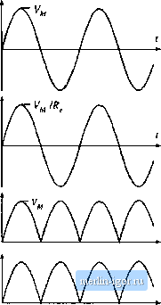  Substitution OfEq. (IS.l i) into Eq. (IS. 14) then leads lo р, Waveforms ofthe metifier system of Fig. 18.3. i(()= y-sin(tuf) (18.15) 2VK. {2ШГ)) Heni;e, the converteroutput current contains a dc component and a component at die second harmonic of the ac line frequency. One of the functions of capacitor С in Fig. 18.3 is to filter oul Ihe second harmonic comptmenl of ((f), so lhai the load current (flowing through resistor /f)is essentially equal to the dc component (18. i6) where 7 is the period of the appiied ae line voltage. The average power is (18.17) The above equations are generally valid for PWM converters used as single-phase low-harmonic rectifiers. 18 J.1 CCM Boost Converter A system based on fhe CCM boost converter is illustrated in Fig. 18.5 [1,5,fi]. Ideally, the boost converter can produce any conversion ratio between one and infinity. Hence, the boost converter is capable of producing the M{d{T)) given by Eq. (18.12), provided that VS V.Further, the boost converter can produce very low TIID, with better transistor utilization than other approaches. If die boost converter operates in continuous conduction raode, and if the inductor is stnall enough diat its influence on the low-frequency cotnponents of the converter waveforms is negligible, dien the duty ratio should follow Midit)) = 1/(1 ~ d{t)). This implies that the duty ratio should follow the fimction (18.18) This expression is true only in the continuous conduction mode. The boost converter operates in the continuous conduction mode provided that the inductor current ripple (18,19) Boost convener Fig. 18.S Rectifier syHlem baK&d Ш1 the bo().4t conveiter. С dz. ко < R 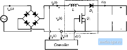 |