
|
| |
|
Строительный блокнот Introduction to electronics is greater than the average inductor current, or Hence, the converter operates in CCM when Substitution ofEq. (18.18) into (18.21) and .solution iniR leads to v/r) for CCM (18.2(1) (18.21) (18.22) Since v{l) varies according to Eq. (18.11), Eq. (18.22) may be satisfied at some points on the ac line cycle, and not at others. Since 0 < v(t) < V/, we can conclude that the converter operates in CCM over the entire ac line cycle when Equations (18.18) and (18.22) then hold for all f. The converter always operates in DCM when R,->- (18,23) (ia.24) For between these limits, the converter operates in DCM when v(l) is near zero, and in CCM when vit) approaches V/, The .static input characteristics of the open-loop boo.st converter arc sketched in Fig. 18.6. The input curi-cnt ijft) is plotted vs. input voltage vjf), for various duty cycles d{r}. In CCIVI, the input characteristics of the boost converter are described by in CCM To obtain a general plot, we can norinahze the input current and inpnt vohage as follows: Equation (18.25) then l>ecomes л.,(/) = 1 - d(!) (18.2.5) (18.26) (18.2.7) (18.28) This equation is independent of the input current ( ((), and hence is represented by vertical lines in Fig. Ktg. 18,6 Static ittput charactetistics of the boost converter. A typical hiicar resistive input characteristic is superimposed. 1 T 0,75 - 0,35 - 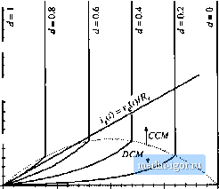 0.25 0.75 18.6. To derive the hoo&t input characteristic for DCM operation, we can solve the steady-state equivalent circuit mode! of Fig. 11.12(b) (reproduced in Fig. 18.7). Beware: the natural DCM effective resistance of Chapter 11, R = 2UdT, does not necessarily coincide with the emuiated resistance Re~ss of Eq. (IS.i). In this chapter, the quantity R is defined according to Etj. (18.1). Soltttton of Fig. 18.7 for theinputcurrent 1,(0 leads to: V-v,(f) The instantaneous power consumed by the effective resistor in the model of Fig. 18.7 is p{t) = Substitution ofliq. (18.30) into Eq. (18.29) and simplification leads to (18,29) (1S,.30) Fig, 18.7 Averaged equivalent circuit model of the bt4>st converter opeintlng in DCM, derived in Chapter 11. 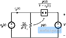 = ill DCM (18.31) Normalization of this equation according to Eqs. (18.26) and (18.27) yields ;,(r)(l-m,(0)=rf4W f *-32) This equation describes the curved (DCM) portions of the Fig. 18.6 input characteristics, for low lj,(()> To express the CCIVI/DCIVI mode boundarv as a function of Сг) and Eqs. (18.1) and (18.22) can be combined, leading to for CCM (18.33) Normalization of diis equation, according to Eqs. (18.26) and (18.27), results in > mlt)[ 1 - init) ] for CCM (18.34) This equation describes a parabolti having roots at - 0 and m = \, with the maximum value f = 0.25 at = 0.5.The mode boundary equation is plotted as a dashed line in Fig. 18.6 The complete input characteristics for the boost converter were plotted in Fig. 18.6 using Eqs. (18.28), (18.32), and (18.34). Figure 18.6 also illustrates the desired linear resistive input characteristic, Eq. (18.1). For the value of/f illustrated, the converter operates in DCM for v(t) near zero, and in CCIVI for Vj(Onear V.Thc intersections of boost input characteristics with the desired linear input characteristic illustrate how the controller must choose the duty cycle at various values of Vj,(f). Other converters capable of producing the M(d{t)) of Eq. (18.12) include the buck-boost, SEPIC, and 6uk converters. The boost, SEPIC, and Cuk converters share the desirable property of nonpulsating input current, and hence icquire minimal input EMI filtering. The SEPIC produces a non inverted output voltage. Isolated versions of these converters (see Chapter 6) are also sometimes employed [7-9]. Schemes involving the parallel resonant converter, as well as several types of quasi-resonant converters, ai-e also documented in the literature [10-13]. Tlie open-loop boost converter, when operated in discontinuous conduction mode, is also sometimes used as an approximation of an ideal i-ectificr. The DCIVI effective icsistance 2L (/)7;ofFig. 18.7 is then taken as an approximation of the desired emulated resistance of Eq. (18.1). The model differs from that of the ideal rectifier model of Fig. 18.1(c) in that the power .source is connected between the input and output terminals. As a resuh, harmonics are present in the input curi-cnt waveform. For example, if Vjff) is a rectified sinusoid, then the current through the cffccdve resistance 2L/cfU)Tt will also be a rectified sinusoid. Howcvci, the input current is now equal to the sum of the current through and the current flowing thiough the power source element. Since the power source is a nonlinear element, contains harmonics. For large C, the output voltage is essentially constant. The input current waveform is then given by Eq. (18.31). If V is sufficiently huge, then the term (1 - v{t)lV) is approximately equal to one, and the harmonics in(f(0)r,are small. The zcio crossings of v{t),pit), and (j.C))?; coincide. So although the DCM boost converter generates sonic current harmonics, it is nonetheless possible to construct a low harmonic rectifier that meets harmonic limits. Again, this approach has the disadvantages of the increased peak currents of DCM, and the need for additional filtering of the high-frcqiicncy pulsating input currents. Computer simulation of a DCM boost rectifier is described in Appendix B, Section B.2.3. |