
|
| |
|
Строительный блокнот Introduction to electronics A similar approaeli is to operate tire boost converter at the boundary between the continuous and discotititiuous conduction modes. This approach is known as critical conduction mode operation. It eliminates the distortion mechanistii described above, but requires variable switching-freqtrency control. This approach is quite poptilar at low power levels, and is described further in Section 18.3.3. Other converters not capable of producing the M{d{t)) of Eq. (18.12), sucli as the buck converter, are sometitlles employed as the dc-dc converter of Fig. 18.3. Distortion of the ac line current waveform must then occur. Nonetheless, at low power levels it may be possible to meet the applicable ac line ctirrent harmonic standards using such an approach. 18.2.2 DCM Flyback Converter In Chapter 11, the loss-free resistor network is used to model converters operating in discontinuous conduction mode. This suggests that DCM converters can also be used as near-ideal rectifiers. Indeed, the buck-boost, flyback, SEPIC, and CwV converters, when operated in discontinuous conduction tnode without additional control, inherently behave as natural loss-free resistors. The DCM effective resistance R, found in Chapter 11 to be equal to lUDT,., then coincides with the rectifier emulated resistance of Eq. (18.1). At low power levels, this can be an effective and low-cost approach. Inrush current limiting is also inherent in this approach, and isolation and scaling via a turns ratio are provided by the transformer. Disadvantages are the increased peak currents of DCM, and the need for additional filtering of the high-frequency pulsating inptit currents. A simple low-harmonic rectifier system based on the transformer-isolated flyback converter is illustrated in Fig. 1 S.8 [2]. The ac line voltage is connected through an input EMI filter to a bridge rectifier and a flyback convener. The flyback converter is operated at constant switching frequency /, and constant duty cycle D. The converter is designed stich that it operates in the discontinuous condtiction mode under all conditions. The input EMI filter smooths the pulsating input current waveform, so that is approxitnately sinusoidal. The flyback converter is replaced by its averaged equivalent circuit in Fig. 18.9. As discussed in Chapter II, the terminal waveforms of the flyback conveiter have been averaged over the switching period 1\, resulting in the loss-free resistor model. This tnodel illustrates how the DCM flyback converter presents a resistive load to the ac input. It also illustrates how the power flow can be controlled, by varia- EMI fiher Flyback converter С <R 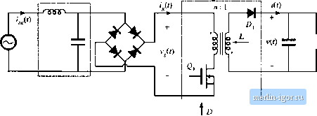 Fig. 18,8 Low-haiDionic rectilier systein iiicorpdiatitig a Ilyback converter that operates in the di.scQntiruousi tnit-duclion mode. EMI filter- Averaged ittodel 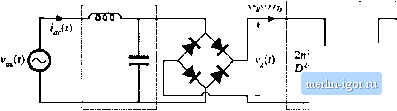 Fig. 18.9 Averaged equivalent circuit that models the sysleiti of Fig, 18.8. lion of D to control llie value ofthe emulaled resistance Д.. To design thi.s converler. one must select the value of inductance to be sufliciently small, such that the converter operates in DCIVI at all points on the ac .sine wave, at maximum load. If we denote the lengths ofthe transistor conduction interval, diode conduction interval, and discontinuous interval as D7j., dT, and rfjT respectively, then the converter operates in DCM provided that d is gtcater than zero. This implies that d[l] <\-D By volt-second balance on ihe transformer magnetizing inductance, we ciui express i,f/) as Substitution ofEq. (18.36) into Eq. (18.35) and solution lor D yields nV j (18.35) £18,36) tlS.37) During a given switching period, the converter will operate in DCM provided that the above inequality is satisfied. The worst с;ъче occurs when the rectified sinusoid i,(/) is equal to its peak value V. The inequality then becomes u<-i- (18.3S) If Eq. (18.38) is satisfied, then the ctmveifer operates in DCM at all points on the tic line sinusoid. In steady state, the dc output voltage is given by Eq, (18.8). Upon substitution ofthe expression for R and solution for D, this equation becomes Insertion of this relaiitmship into Eq. (18.38), and solution for L, yields 4S Pulse-Wm Modulated Reaifierji 77717; (18.40) For variations in load R and peak ac input voltage Vj, the worst ca.se will occur at ininimum R (пулы-mum power) and minimum V. Hetice, the de.signer should choose L to satisfy (18.41) If this eqtiatton is violated, then at ma.\.imum load power and minimum inpul vollage amplitude, the convert will operate in CCM near the peak of the ac sinewave. This will lead to an input currenl waveform having subslanlial disioriion. 18.3 CONTROL OF THE CURRENT WAVEFORM A wide variety of approaches are known for active control of the input currenl waveform lo attain input resistor emulation [14-33J. Average currenl control [17,lSj, input voltage feedforward [17j, current-programmed control [19-22], hysieretic control and critical conduction mode control [23-27J, iind nonlinear carrier control [28-30] are briefly surveyed here. Other approaches include sliding-mode control [31], charge control [32], and ASDTIC control [33]. 18.3.1 Average Current Control Average current control is a popular method of implementing control of the input current waveform in a low-harmonic rectifier. This approach works in both continuous and di.scontinuous conduction modes, and can produce high-quality current waveforms over a wide range of input voltages and load powers. The problems of crossover distortion, found in some competing schemes such as current programmed control, are largely avoided. Several popular integrated circuits are available that implement average current control. Figure 18.10 illustrates average current control of the input current waveform (/0),j in a boost converter. The input current lj,t) flows through a shunt resistor. The voltage across this shunt resistor is amplified by an op amp circuit. This op amp circuit contains a low-pass filter characteristic that attenuates the high-frequency switching harmonics. The output voltage v (/) of the op amp circuit is pR>por-tional to the low-frequency average value of /,(0: v (f) = /f,(i,(f)) (18.42) This signal is compared to the reference voltage v,(0. to produce an error signal that drives the compensator network and pulse-width modulator as illustrated. If the feedback loop is well designed, then the error signal is small: f (f)-i,(0 (плъ) |