
|
| |
|
Строительный блокнот Introduction to electronics Boost converler  v,(0 Multiplier j ТПЛР С dp v{o < Д G,{s} Compensator Controller Fig, 18,11 Average current control of a boost converter, to obtain a low-harnionit rectifier. Tbe average current controller causes tlte sensed current ij,t) to Follow tlte reference waveforin vj,t). To cause the input current to be proportional to the input voltage, the reference voltage vjif) is derived from the sensed input voltage waveform, as in Fig. 18.11. The current reference signal vt) is derived from the sensed input voltage v(0, and hence has a sinusoidal waveshape. Hence, the average current controller causes the average input current iU) to be proportional to the input voltage v/O- The multiplier illtistrated in Fig. 18.11 allows adjtistnicnt ofthe con.stnnt of proportionality, so that the magnitude of the emulated resistance can be controlled via a control signal гоигтК- Let us assnmc that the multipher terminal equations are Fig, 18,1(1 Average current control of the input current in a boost converter. Current sense circuit 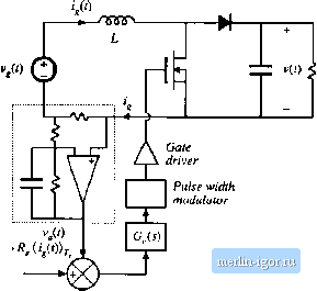 Compensator Current reference Ideal rectifier (LFR) С Ф Ш-, < R 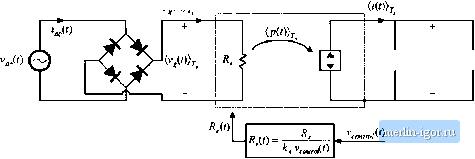 Pig. 18.12 Model оГ the system of Fig. [8.5, based iin (tie loss-free resistor inotlel of Fig, I K.l<cJ, whieh predieis the low-fiequeiicy system waveforms. This inodel a.ssumes lhal the feedback looji of Fig. I Й,5 operates ideally. (18.44) Then the emulated iresistance is *.v , (i) (18.45) v (f) Here, Eqs. (18.44) and (18.42) have been used toelitiiinate f, and i. Substitution ofEq. (18.43) leads to the result (18.46) Hence, if the feedback loop is well designed, then the system of Fig. 18.11 can be represented by the LFR mode! as in Fig. 18.12. The average current controller scheme of Fig. 18.11 and the model of Fig. 18.12 are independent of the dc-dc converter topology, and can be applied to systems containing CClVl boost, buck-boost, Uik, SEPIC, and other topologies. Average power flow and the output voltage are regulated by variation of the emulated resistance R, in average current control as well as in most other schemes, This is usually accomplished by use of a multiplier in the input voltage sensing path, as shown in Fig. 18.13. This control loop continually adjusts R, to maintain balance of the average rectifier power = .гтУг hs load power -fjj. such that the following relation is obeyed: (18.47) Average current control works quite well. lt.s only disadvantages are the need to sense the average input currenl, rather than the transistor current, and the need for a multiplier in the controller circuit. Most average current control implementations include provisions for feedforward of the input voltage amplitude. This allows disturbances in the ac input voitage amplitude to be canceled out by the 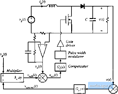 vohage reference W<0 Fig, 18,13 Avcrilge current contrtil incorporating a multiplier for regulation cif the ouiput voltuge. conltolier, sucli llml tlie dc outptit voltage is unallected. Combination of Eqs. (18.44), (18.46), and (18.47), and solution lor vU) leads to 7..1,(/)Я, (18.48) This equation shows how the reference voltage should be varied to maintain a given rectifier average power throtighput 7,. Apparently, it is necessary to divide by die square of the mis inptit voltage amplitude. A controller lhat implements Ec], (18.48) is illtistrated in Fig. 18.14. The multiplier block of Fig. 18.13 has been generalized to perform the lunclioii kxyh}. It is somewhat cttmphcated lo coraptile the rms value of a genertti ac waveform; however, the ac input voltage vt) nomiaily is sinusoidal with negligible harmonics. Hence, the peak value oivjif) i.s directiy proportional to its rms value, and we can use the peak valtie in place ol . So the controller ol Fig. 1K. 14 produces the reference voltage (18.49) Comparison of Eqs. (18.48) and (18.49) leads lo the concitision that 2ft, (1Я.50) So the average power throughput is directiy controlled by ,д, (/), and is independent of the inpul voltage v((). Feedlorwiud can cause the rectifier dc otitptit voltage to be less sensitive to viuiations in the ac |