
|
| |
Строительный блокнот Introduction to electronics 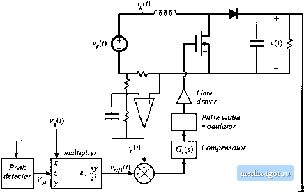 Fig, 18,14 Average current eniitn)! incorporatitig input voltage leodlorward, line vollage. A disadvantage is the ac line current distortion introduced by variations in the vollage produced by the peak detector. To aid in the design of the inner feedback loop that controls the ac line currenl waveshape, a converter model is needed that describes how the cttnverler average inpul current depends on the duty cycle. We would prefer to apply the avetaged small-signal modeling techniques of Chapter 7 here. The probiem is that the variations in the duty cycle d{j\, as well as in the ac input voltage v(f) and current are not smaii. As a resuit, in general the stnaii-signal assutnptions are violated, and we aie laced with the design of acontrol system lhal exhibits significant nonlinear lime-varying behavior, When the rectifier operates near periodic steady slate, the output voitage i(f) of a weli-designed system exhibits small variations. So we can write (vW) I + vtf) wilh ад :! (18..>2) In odier words, the small-signal assumption continues to be valid with respect to the rectifier output voltage. In the case of the boost converter, this allows us to linearize the converter inpul characteristics. Following the approach of Chapter 7, we can express the average inductor vollage of the boo.st converter as Fig. 18.15 Linearized inodel describing the boost [;onverter inptit eharacteristics, corresponding to Eq. (18.55)  I- -l = (V>) -(0(v(r)}, (1S.53) This equation contains the nonlinear term d{t) (i(r)),.. Substitution of Ecj. (18.51) into (18.53) yields L / = {v,(f)) - dXt] V-d!U)m (tK.54) When Eq. (18.52) is satisfied, dien the nonlinear tertrt - d{t)v{t) is much smaller in magnitude than the linear term - (f(f)K Therefore, we can discard the nonlinear tenn to obtain dhit)) Lj{,{t))..-tl4,)V (18.55) This linear differentia] equation is valid even though i,(0, v,((), and dif) contain large variations. An equivalent circuit corresponding to Eq. (18.55) is given in Fig. 18.15. The averaged control-to-input-curieiit transfer function is found by setting the independent inputs other than dif) to zero, and then solving for i; the model predicts that tliis transfer function is dis) V sL (IS.56) where i(s) is the Laplace transform of (/(f)). So the input characteristics of the boost rectifier can be linearized, even though the nc input variations are not small. Unfortunately, Eq. (18.52) is not sufficient to linearize the equations describing the input characteristics of the buck-boo.st, SEPJC, Cuk, and most other single-phase rectifiers. The ctintrol systern design engineer must then deal with a truly nonlinear time-varying dynamical .system. One approach that is sometimes suggested employs the quasi-static approximation [34.35]. It is asstimed that the ac line variatitins are much slower than the rectifier system dynamics, such that the rectifier always operates near equilibrium. The quiescent operating point changes slowly along the input sinusoid; an equilibrium analysis can be performed to find expressions for the slowly-varying equilibrium duty ratio and converter voltages and curtents. The small-signal dc-dc converter tr;msfer functions derived in Chapters 7 and 8 are evaluated using this time-vaiying operating point. The conveiter poles, zeroes, and gains are found to vaty along the ac input sinusoid. An average curtent controller is designed using these time-varying transfer ftinctions, such that the current loop gain has a positive phase margin al ail operating points. We expect that the quasi-static approximation should lie valid if the rectifier system dynamics are sufficiently fast, and it is reasonable to anticipate Lhat high-frequency PWM converters have dynnin- ICS lhai are much faster than the ac line ftecjuency. The problem is that no good condition on system parameters, which can justify the approximation, is known lor the basic converter topologies. There is room for additional research in this area. It is well-understood in the field of control systems that, when the rectifier system dynamics are not sufficiently fast, the quasi-static approximation yields neither sufficient nor necessary conditions for stability of the resulting design. Time-varying loop gains that always have a positive phase margin may nonetheless be unstable, and a negative phase margin does not always imply instability. Such phenomena are sometimes observed in rectifier systems. Even worse, it is difficult to justify the use of the Laplace transform on rectifiers described by time-varying differential equations, unless the quasi-static approximation can be validated. 18.3,2 Current Programmed Control Another well-known approach to attaining input resistor emulation is the use of cuirent-programmed control. As illusuated in Fig. 18.16, the programmed cuirent /ДО is madeproportional to the ac input voltage. This causes the average inductor cunent, and hence also ((O),-. to approximately follow v{i}. As in average current control, a multipliei is u.ied to adjust the emulated resistance and average power flow; the control signal c , ,(i) is typically used to stabilize the dc output voltage magnitude. Several rectifier control iCs aie commercially available, which implement current-programmed control. As discussed in Chapter i 2, several mechanisms cause the average inductor current and hence also {!j,(f))); to differ from the programmed ij,f). These mechanisms introduce crossover distortion and line current haimonics. An aitificial ramp having sufficiently large slope wt is necessary to stabilize the Boost converter сгиЛпЛ V/t) Multiplier 1*2(0 ,(0 v{t) < R ijf) Clock <1 T fCO Corjtparaior S Q R Ijitch Carrctit-progratntned controller Fig. 18.16 Currem-progiiiinmed coutinl of a boost j-cttiiJcr. |