
|
| |
|
Строительный блокнот Introduction to electronics CLirrent-programmed boost converter when it operates in CCM with t.l(t) > O.S. The addition of this ramp causes 0(0), to differ from Additional deviation is introdticed by tlie inductor currem ripple. Botli mechanisms are most pronounced wlien tlie inductor current is small, near tlie zero-crossings of the ac line waveforms. The static itipttt charactetistics, that is, the average input cutiEnt vs. the input voltage, of the current-programmed boost converter are given by , in DCM (18.57) T in CCM The converter operates in the continuous conduction mode when 2L V In terms of the control current iit), tlie condition for operation in CCM can be expressed (18.58) mj. vit) (18.59) In the conventional current-programmed rectifier control scheme, the control current ij,t) is simply proportional to the ac input voltage: (18.60) where is the emulated resistance that would be obtained if the average input curretit exactly followed the reference ctirrent !;,(0. The static inptit characteristics given by Eqs. (18.57) to (18.60) are plotted in Fig. 18.17. The average input current is plotted as a function of the applied inptit voltage v/f), for several values of etuulaied resistance The regioti near the CCM-DCM boutidary is shown. The curve.s are plotted for a fixed artificial ramp having slope (18,61) This is the tninitnum value of artificial ramp that stabilizes the boost current-programmed controller at all static operating points. Decreasing m below this value leads to instability at operating points in the contintious conduction mode at low vjityv. To obtain resistor emulation, it is desired that the static input characteristics be linear and pass through the origin. It can be seen from Fig. 18.17 that this is not the case: the curves are reasonably linear ill the cotititutotts conduction mode, bttt exhibit significant curvature as the CCM-DCM boutidary is approached. The resulting average current waveforms are stiramarized in Fig. 18.8. To minimize the line current THD, it is apparent that the converter should be designed to operate deeply ill the continuous conduction mode for most ofthe ac line cycle. This is accomplished with emulated resistances R. that are much smallerthan Л = 2UT. In addition, the artificial ramp slope m 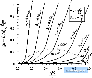 Fig, 18.17 Static input cliaracteristics of ftcurreiit-prugramined boost converter, witli niiiiimuni stabilizing artili-eial ramp of Eq. (18,61). Peak i. 1.0 T 0.3 -- 0.6 -- 0.4 - 0.2 - ff 2L 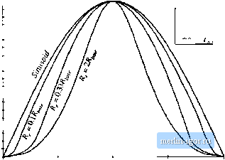 Fig. 18.18 input current wave.shapes predicteci by the static input eliaracteristies of Pig. 18,17, compared with a pure sinusoid. Curves are plotted for the case v-o.sv, with minimum stabilizing artificial imp. should be no greater than otherwise necessary. In practice, THD of 5% to 10% can easily be obtained in rectifiers that function over a narrow range of rms input voltages and load currents. However, low THD cannot be obtained at all operating points in universal-input rectifiers; THD of 20% to 50% may be observed at maximum ac input voltage. This problem can be solved by biasing the current reference waveform. Design of current-programmed rectifiers is discussed in [19-22], and some strategies for solving this problem are addressed in [19]. 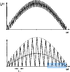 Fig, 18.19 Input current waveforms of two boost converters with hysteretic contrtil; (a) ± 10% regulation band, (b; critical conduction mode operation (± 100% regulation band). IS.3.3 CtiticaJ Conduction IModc and Hvstcrctic Control Another control scheme sometimes tised in low-harmonic rectifiers, as well as in dc-dc converters and dc-ac inverters, is hysteretic control. Rather than operating at a fixed switching freqtiency and duty cycle, the hysteretic controller switches the transistor on and off as necessary to maintain a waveform within given limits. A special case of hysteretic control, called critical conduction mode control, is implemented in several commercially-available ICs, and is popular for low-harmonic rectifiers rated below several hundred Watts [23-25]. An example is the sinusoid of Fig. 18.19(a), in which the boost converter input current is controlled to follow a sinusoidal reference with a ± 10% tolerance. The indtictor current increases wlien the transistor is on, and decreases when the transistor is off. So this hysteretic controller switches the transistor on whenever the input current falls below 90% ofthe reference input. The controller switches the transistor off whenever the inptit current exceeds 110% ofthe reference. Hysteretic controllers tend to have simple implementations. However, they have the disadvantages of variable switchitig frequency and redticed noise immunity. Another example of hysteretic contral is the waveform of Fig. 18.19(b). The lower limit is chosen to be zero, while the tipper limit is twice the reference input. This conb-oller operates the Iwost converter at the boundary between the contintiott.s atid di.scontinttoti.s conduction modes. An alternative contral scheme that getierate.s the same waveform .simply operates the transistor with cotistant on-time: the transistor is switched on when the itidttctor current reaches zero, and is switched off after a fixed |