
|
| |
|
Строительный блокнот Introduction to electronics Hg. 18.24 Waveforms of a singie-phase ideal rectifier system: (a) pulsaiitig ac input power p,.(/), and canstant dc load power P; (b) energy storage capacitor voltage v(t). 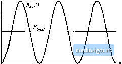 as an electrolytic capacitor. The difference between the instantaneotjs input and load powers flows through this capacitor. The waveforms of rectifier systems containing reactive elements can be determined by solution of the rectifier energy equation [J6,37]. If the energy storage capacilor С is the only system element capable of significant low-frequency energy storage, then the power pfj) flowing into the capacitor is equal to the difference between the instantaneous inpul and output powers: Pc<0 = Pjn-P, Jt) (18,85) where С is the capacitance, Vfit) is the capacitor voltage, and £(,(/) is the energy stored in the capacitor. Hence as illustrated in Fig. 18.24(b), when pJit) >Pi j(t) then energy flows into the capacilor, and v-U) increases. Likewise, v(t) decreases when pJ,t) < Piaad capacitor voltage V(-(f) musl be allowed to increase and decrease as necessary to store and release the required energy. In steady-state, the average values of pJ,t) and Pj,i(.t) must be equal, so that over one ac line cycle there is no net change in capacitor stored energy. Where can the energy storage capacitor be placed. It is necessary to separate the energy storage capacitor from the regulated dc outpui, so lhal the capacitor voltage is allowed lo independently vary as illustrated in Fig. 18.24(b). A conventional means of accomplishing this is illustrated in Fig. 18.25. A second dc-dc converter is inserted, between the energy storage capacitor and the regulated dc load. A wide-bandwidth feedback loop controls this convener, to attain a well-regulated dc load voltage. The capacitor voltage (f) is allowed to vary. Thus, this system configuration is capable of(l) wide-bandwidth control of the i\c line current waveform, to auain unity power factor, (2) internal low-frequency energy storage, and (3) wide-bandwidth regulation of the dc ouipul vollage. It is also possible to integrate these functions into a single converter, provided that the required low-frequency independence of the input, output, and capacitor voltages is maintained [38j. The energy storage capacitor also allows the system to function in other situations in which the insiamaneous inpui and outpui powers dilTer. For example, it is commonly required thai the output voh- Ideal rectifier {LFR} ((j 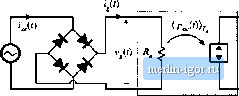 Dc-dc converter V(!) load Energy storage capacitor Fig. 18.25 Elements ol a singie-phase-ac to dc power supply, in whicli tine ac line currant and dc toad voltage are independently regulated with high bandwidth. An iuterual independent energy storage capacitor is rdquired, age retiiain regulated during ac line voltage failures of short duration. The hold-up time is the duration lhat the otitput voltage v{i} remains regulated after у Д/) has become zero. A typical requirement is that the system continue to supply power to the load during one complete missing ac line cycle, that is, for 20 msec in a 50 Hz system. During the hold-up time, the load power is supplied entirely by the energy storage capacitor. The value of capacitance should be chosen such that at the end of the hold-up titne, the capacitor voltage v(i) exceeds the mininiuni value that the dc-dc converler requires to produce the desired load voltage. The energy storage funclion could be performed by an element otherthan a capacitor, such as an inductor. However, use of an inductor is a poor choice, because of its high weight and cost. For example, a 100 100 V electrolytic capacitor and a 100 цН 100 A inductor can each store 1 Joule of energy. But the capacitor is considerably smaller, lighter, and less expensive. A problem introduced by the energy storage capacitor is tlie large inrush oirrent observed during the system turn-on transient. The capacitor voltage v(t) is initially zero; substantial amounts of charge and energy are required to raise this voltage to its equilibrium value. The boost converter is not capable of limiting the magnitude of the resulting inrush current: even when d{i) = 0, a large current flows through the boost converter diode to the capacitor, as long as the converter output voltage is less than the input voltage. Some additional circuitry is required to limit the inrush current ofthe boost converter. Converters having a buck-boost type conversion ratio are inherently capable of controlling the inrush current. This advantage cotnes at the cost of additional switch stress. It is also possible to design the ideal rectifier to operate correctly when connected to utihty power systems anywhere in the world. Universal input rectifiers can operate with nominal ac rras voltage magnitudes as low as the 100 V encountered in a portion of Japan, or as high as the 260 V found in western Australia, with ac line frequencies of either 50 Hz or 60 Hz. Regardless of the ac input voltage, the universal-input rectifier produces a constant nominal dc oulpul voltage V Let us now consider in more detail the low-frequency energy storage process of the system of Fig. 18.25. Let us assume that the dc-dc converter contains a controller having bandwidth much greater than the ac line frequency, such that the load voltage contains negligible low-frequency variations. A low-frequency model ofthe dc-dc converter is then as illustrated in Fig. 18.26. The dc-dc converter produces constant voltage v{t) = V. modeled by a voltage source as shown. This causes the load lo draw constant current /(/) = /, leading to load power p, a,jif) = li, id- extent that converter losses can be neglected, the dc-dc converter input port draws power Рщ;, regardless of the value of vf). So the dc-dc converter input port can be modeled as a constant power sink, of value it- The model of Fig. 18.26 implies that the difference between the rectifier power р Дг) and the load power flows into the capacitor, as given by Eq. (18.85). The capacitor voltage increases when pjif) exceeds Pi , and decreases when pii) is less than P( , In steady state, the average values of pjif) and Pf must be equal. But note that is determined by the magnitudes of vft) and R, and VI-P, 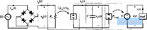 Ideal rectifier (LFR) Energy storage De-dc capacitor converter Kig. 18.i*l Lt)w-frequc[)cy equiviileiit cirouil of the syslcm of Fig. 18,25. nul by (tie load The .system of Fig. 18.26 cotiiains no mechanism to cause the average reciifier power anii load power to be equal. In consequence, it is necessary to add an additional control system that adjusts as necessary, to catise the average rectilier output power and dc-dc converter input power to balance. The conventional way to accomplish this is simply to regulate the dc coinponent of vit). A complete system containing ideal rectification, energy .sttnage, and wide-bandwidth output voUage regulation is illustrated in Fig. 18.27. This system incorporates the boost converter and controller of Fig. 18.5, as well as a generic dc-dc converter with ouipul voltage feedback. In addition, the system contains a low-bandwidth feedback кюр, which regulates the dc ctmiponent of the energy-storage capacitor vollage to be equal to a reference vollage V .. This is accomplished by slow variations of .д, щ({0 and R. This controller should have sufficiently small loop gain al the even harmonics of the ac line frequency, so lhal variations in are much slower than the ac line frequency. Increasing the bandwidth of the energy storage capacitor voltage controller can lead to significant ac line current harmonics. When this controller has wide bandwidth and high gain, then it vEiries ДДО quickly, distorting the ac line current waveform. In the extreme limit of perfect regulalion of the Boctsi converter v (0 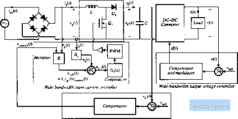 Loiv-bandwidfh fnergy-storsge capacitor voitage centrvtUr Fig. 18J7 A complete dc power supply aysieni incorporating a neiu--i(leal single-phase Vxiosi rectifier system, energy storage capacitor, and dc-dc converter Wide-bandwidih feedback loops regubte the ac line current waveform and the dc load vohage, and a slow feedback loop regulates the energy .storage cupacilor vollage. |