
|
| |
Строительный блокнот Introduction to electronics 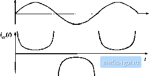 Fig. 18,28 Ac line currstit wjivcloriii of tlie single-phase ideal rectifier with ouiput voltage feedback, when ii siip-pllc.4 constant instaiuaneous power to adc loaJ, Tiie THD tends to infinity, and the power factor tends to zero. energy storage capacitor voltage V(-(/) = V., then the capacitor Stored energy is constant, and the instantaneous inpul ac line power р Д/) and load power P; (/(f) are equal. The controller prevents the energy-storage capacitor Irora performing its low-frequency energy storage function. The ac line current then becotnes (18.86) Tliis waveform is sltetched in Fig. 18.28. In this idealized limiting case, the ac line current tends to infinity al the zero crossings of the ac line voltage waveform, such lhat the instantaneous input power is constant, ll can be shown that the THD of this current waveform is infinite, and its distortion factor and power factor are zero. So the bandwidth of this controller should be limited. The energy storage capacitor voltage ripple can be found by integration ofEq. (IS.85). Under steady-state conditions, where the average value of / (0 = Я, , integTation of Eq. (18.85) yields = 5 CvlU) = E,iO) 4 [ (- Г; ,cos(2w))Л where OJis the ac line frequency. Evaluation ofthe integral leads to £,(,) = £,((.) Therefore, the capacitor voltage waveform is (18.87) (18.88) (18.89) It can be verified that the rms value of this waveform is = V(,{0). Hence, Eq. (18.89) can be written vc(f) - Vr .,. / 1--:sm {2ш) (iS.90) This waveform is sketched in Fig. 18.24(b). The minimum and maximum values ofthe capacitor vohage occur when sin (2ш) is equal to 1 and -1, respechvely. Therefore, the peak-to-peak capacitor voltage rip- pie is (18.9!) The approximation is valid lor / ./(шСс, !!) sufficiently less than one, a condition that is satisfied whenever the ac vollage ripple is sufficiently less lhan 18.4.2 Modeling the Outer Low-Bandwidth Control System As discussed above, lhe outer low-bandwidth controller, which varies the emulated resistance as necessary lo balance the average ac input and dc load powers, is common to all near-ideal rectifier systems. For design of this controller, the rectifier can be miKleled using the loss-free resi.sior (LFR) mtKlel. Perturbation and hnearization of the LFR leads to a small-signal equivalent circuit that predicts the relevant small-signal transfer functions. Such a model is derived in this section [2,39,40]. It is desirable to stabilize the rectifier output voltage against variations in load power, ac line vollage, and component characteristics. Hence, a voltage feedback loop is necessary. As discussed in Section 18.4.1, this loop cannot attempl lo remove lhe capacilor voltage ripple lhat occurs at the second harmonic of the ac line frequency, 2ш, since doing so would require that ,(0 change significantly at the second harmonic frequency. This would introduce significant distortion, phase shift, and power factor degradation into the ac line current waveform. In consequence this loop must have sufficiently small gain at frequency 2ю, and hence its bandwidth must be low. Therefore, for the purposes of designing the low-bandwidth outer control loop, it is unnecessary to model the system high-frequency behavior. It can \x, assumed that any inner wide-bandwidth controller operates ideally at low frequencies, such that the ideal rectifier model of Fig. 18.2У(а) adequately represents the low-frequency system behavior. A small-signal model is derived here that correctly predicts the control-to-output transfer function and output impedance of any rectifier system lhat can be modeled as a loss-free resistor. The model neglects the complicating effects of high-frequency switching ripple, and is valid for control variations at frequencies sufficiently less than the ac line frequency. Both resistive and dc-dc converter/regulator loads are treated. The steps in the derivation of the small-signal ac model are summarized in Fig. 18.29. Figure 18.29(a) is the basic ideal rectifier model, in which the converter high frequency swilching ripple is removed via averaging over lhe switching period T, but waveform frequency components skiwer than the switching frequency are correcdy modeled, including the 2ff secotid-harmonic and dc comptments td output voltage. Et is difficult to use this tnodel in design of the feedback loop because it is highly nonlinear and time-varying. If the ac input voltage vf) is sin or v.(r) = vv,. then the model of Fig. 18.29(a) predicts that lhe instantaneous output power {р{1)\ is (18.92) r, (. , ,.4 (18.93) Ideal rectifier (LFR) 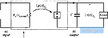 Rectifier output port (2(f)) Load Rectifier outpul port
82У, Cdp i> R < Riictifier ouiput port Fig. 18.2! Steps in the derivation of low-frequency small-.signal rectifier model: (a) large-signal LFR model, averaged ever one switcliing period T; (b) separation of power source into its constant and lime-varying components; (c) removal of second-harmonic componenis by averaging over One-half Of ihe aC line period, 7j; (d) small-signal model obtained by perturbation and linearization of Fig. IS.29(c). |
||||||||||||||||||||||||||||||||||||||||||||||||||||||||||