
|
| |
|
Строительный блокнот Introduction to electronics 676 Fulse-WiM Moditlased Reclifiers / =0 92/ (18.122) Larger values of У lead lo smaller rms diode currenL Average currents can be computed in a similar way. The results are / -I 2й: (lti.!2.} 2/2 V Expressions for rms, average, and peak currents of the power stage componetits of the continuous conduction mode boost converter are .summarized in Table 1 S.3. Expressions are also tabulated for flyback and SEPIC topdogies, operating in the continuotis conduction mode. In the case of the flyback converter, an i-i-Ci input filter is also included, [n all cases, lhe effects of swilching ripple are neglected. 18,5 J Comparison of Single-Phase Rectifier Topologies When isolation is not a rectifier recuirement, and when it is acceptable that the dc output voltage be marginally larger lhan the peak ac input vollage, then the boost converter is a very effective approach. For example, consider the design of a 1 kW rectifier operating from the 240 Vrms inpul line voltage. If the converter efficiency and power factor are bolh approximately unity, then the rms input current is = (1000 W)/(240 V) = 4.2 A. The dc output voltage is chosen to be 380 V, or slightly larger than the peak ac input voltage. By use of Et). (18.119), the rms transistor current is found to be 2 A. This is tjtiite a low value-less than half of the rms input current, which demonstrates how effectively the converter utilizes the power switch. The rms diode current is 3.6 A, and the transistor and diode blocking voltages are 380 V. With a [20 A ac input voltage, the transistor and diode rms currents increase to 6.6 A and 5.1 A, respecdvely. The only real drawback of the boost converter is its inability lo limit inrush currents. When the dc outpui voltage is less lhan lhe instanianeous input voltage, the control circuii of the btxMt reciifier loses control of the inductor currenl waveform. A very large inru.sh current occurs when the dc output capacilor is initially charged. Additional circuitry must be employed lo limit lhe magnilude of this current. Buck-boost, SEPIC, and Cuk topologies can be used to solve the inrush current problem. Since these converters have a d/(] - d) conversion ratio, their waveforms can be controlled when the output voltage is any positive value. But the price paid for this capability is increased component stresses. For the same [ kW reciifier with 240 Vrms ac input and 380 V output, the transistor rms currenl and peak voltage of the nonisolated SEPIC are 5.5 A and 719 V. The rms diode current is 4.85 A. The semiconductor voltage stoesses can be reduced by reducing lhe output voltage, al the expense of increased rms currents. With a 120 V ac inpul voltage, the iransistor and diode rms currents increase to 9.8 A and 6.1 A, respectively. Isolation can also be obiained in the SEPIC and other topologies, as discussed in Chapter 6. The turns ratio of the isolation transformer can also be used to reduce the primary-side currents when the dc output vollage is low. But the transformer winding rms currents are higher than those of a dc-dc converter, because of the pulsating (iwice-line-frequency) power llow. For the 1 kW, 240 V ac inpul SEPIC example, wilh a 42 V 23.8 \ dc load, and a 4:1 transformer turns ratio, the rms transformer currents are 5.5 A (primary) and 36.4 A (secondary). The rms transistor cturent is 6,9 A. At 120 V ac input voltage. Table 18.3 Summary of rectifier current stresses for several converter topologies tins Average Peak CCM boost Transistor Diode Inductor acmu !nj2 CCM flyback, with n: 1 isolation tttisfonner and input filter Transistor, fmr primly ,77x Зя nV Diode, xfmr secondary +J /vmaxll,; 2f(l + f CCM SEPIC, nonisolated Transistor Diode 2 Зя V 1 + . CCM SEPIC, with Tt: 1 isoladon transformer Transistor i C[, xfmr primary Diode, xfmr secoiKlary v * Зтс r 2/2 It widi, in all cases, = -JtT i*? voltage = ViAaiiai). dc output voltage = V ay these currents increase to 7.7 A, 42.5 A, unti 11.4 A, respectively. 18.fi MODELING LOSSES AND EFFICIENCY IN CCM HIOH-QUALITV RECTIFIERS As in the case of dc-dc converters, we would like to model the cunverter loss elements so that we can coLTeclly specify the power stage components. The equivaleni circuit approach used in the dc-dc case can be generalized lo include ac-dc low harmonic rectifiers, allhough the resulting equations are more complicated betau.se of the low-frequency ac modulalion of the waveforms. A dc-dc boosl converter and its steady-state etjuivalent circuit are illtistrated in Fig. 18.32. When lhe convertei operates in equilibrium, the model of Fig. 18.32(b) can be solved tu determine the converler losses iind efficiency. In the ac-dc case, the input voltage vr) is a rectified sinusoid, and lhe contrt)ller varies the duly cycle d(t) to cause iU) lofollow viO according to (18,124) The emulated resistance is chosen by the coniroller such that the desired dt output volliige is obiained. .c variations in d(f), ij,(0. and several other system wiiveforms are not stnidl, iind hence the small-signal appro.imation employed in Chapler.4 7 lo 12 is uot justified, We cau continue to model the low-frequency components of the converter via averiiging, but the resulting equiviilent circuits iiie, in general, time-varying and nonliiteiu. For the purposes of determining the rectifier efficiency, it is iissumed ibid (1) the inductor is sufficiently small, such that it has negligible inlltience on the ac-line-lrequency cotnponents of the system waveforms, iind (2) the ciipiicitor is liirge, so lhal the otttpul voltage v (t) is essenlially equid to its equilibrium dc vidue, with negligible low- or high-frequency ac variations. So in the ac-dc case, the model becomes as shown in Fig. 18.33. Low-frequency components f) oi the controller waveforms are sketched in Fig. 1834. 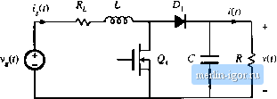 t,(0 -ЛЛг- -AV- Zy : I Fig. 18,32 Dc-dc boost converter, (a), and a steady-state equivalent circuit, (b), which models the inductor resistance R, MOSFET oii-rcsistanctt R, and diode forward voltage drop V.. |