 | |
|
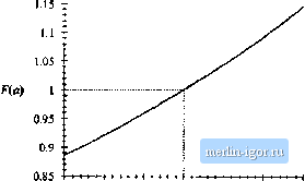
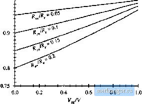
Строительный блокнот Introduction to electronics Now subsiituie v/0= Vv integrate lo find ),: sill (tOfl (8.133} Again, 7]. = 27ttoii the at iine period. Equation (i8.133) tan be rewritten as (iS,n4) where (18.135) By waveform symmetry, we need only integrate from 0 to T,J4. Also, make the substitution 9 = Cdf; sin=(0} 1 -Л51п{0] (18.136) Evaluation of this integral is tedious. It arises in not only the boosl rectifier, but in a number of other high-quality rectifier lopologies as well. The derivation is nol given here, but involves the subslitulion z =1ап(в/2), performing a partial fraction expansion of the resulting rational function of:, and integra-lion of lhe results. The solution is: --Ц-(/о = я ) = 4- -2a-n + 4 sin (и)-I-2cos-1 [ti] (18.137} This equation is somewhat complicated, but it is in clo.sed form, and can easily be evaluated by computer spreadsheei. The quantity a, which is a measure of lhe loss resistance R relative to the emulated resistance R, is typically much smaller than 1. F{a) is plolied in Fig. 18.36, The function F{a) can be well-approximated as follows: F{tt)=\ -l-O.SS2ti4 0.78(r (18,138) For 1я1 < 0.15, the F(d) predicted by this approximate expression is within 0.1% of the exact value. If the fl term is omiiied, then lhe accuracy drops to ± 2% over lhe same range of я. The reciifier efficiency f) calculaled in the next seclion depends directly on Fia], and hence the accuracy o{Fia] coincides with the accuracy of т].  -0.15 -0.10 -0.05 0.00 0,05 0.10 0,15 Fig. 18.36 Plot of the integral Яя) vs. a. IS.6.3 Sttlutittn for Converter Effidenty r Now that we have found the dc load current, we cati calculate the converter efficiency r\. The average inpul power is The average load power is Vli.. where Here, we have stibsiiittied Eq. (18.136) for/. The efficiency is therefore (18,139) (18.140) (18,141) (18,142) by stibstiitilion of Eqs. (18.139) and (18.140). If desired, the parabolic approximation for F(a), Eq. (18.138), can be employed. This leads to (1н.143) Equations (18.142) and (18.143) siiow how the efficiency varies with MOSFET on resistance l< and  0.95 0.85 Fig. 18.37 Boost reclifiet efficiency, liq, 08,142), accounting for MOSFET on resistance, with ac peak voltage V. Equadon (18.142) is plotted in Fig. 18.37. It can be seen that high efficiency is obiained when the peak ac line voltage V, is close to the dc outpui vollage V. Efficiencies in the range 9(Ш to 95% can then be obiained, even with MOSFET on-resistances as high as (i.2R. Of course. Fig. 18.37 is optimistic becanse it neglects sources of loss other than the MOSFET conduction loss. 18,6,4 Design Example Let us utilize Fig. 18.37 to design for a given efficiency. Consider the following specifications: Output voltage 390 V Output power 500 W rms inpul voltage 120 V Efficiency 95% Assume that losses other than the MOSFET conduction loss are negligible. The average input power is The emulated resistance is therefore < (l20V)i27 4n Also, V i20yTV Q435 V 390 V (18.!44) (18.145) (1я.М6) Еют Fig. 18.37, or by evaluation of the exact equation (18.142), 95% efficiency wnth V,/V = 0.435 occurs with R JR ~ 0.077. So we require a MOSFET having an on-resistance of |