
|
| |
Строительный блокнот Introduction to electronics
Fig. 4.7 Operatint; points of switch Л, (a), and switch li, (1)), in tiic htick convcitcrof Fig, 4.2(b), Figure 4.8 is an example of a single-quadrant switch realization: the devices are capable of conducting current of only one polarity, and blocking voltage of only one polarity. When the controller turn.4 the tratisistor on, the diode becomes tevetse-biased sttice Vfl = -V. It is required that be positive: otherwise, the diode will be forward-biased. The transistor conducts current /, This current should also be positive, so that the tratisistor conducts in the forward direction. When the ctmtroller turns the transistor off, the diode tnust turn on so that the itiductor current can continue to flow. Turning the transistor off causes the inductor current ((0 to decrea.se. Since v{t) = Ldtijydt, the itiductor voltage becttmes sufficietitly negative to forward-bias the diode, and the diode turns on. Diodes that operate in this tnanner are sotuetinies called/rrav/iM/in diodes. It is required that i, be pttsitive; otherwise, the diode cimnot be forward-biased since i = if. The transistor blocks voltage this voltage should be positive to avoid operating the transistor in the reverse blocking mode.  Fig. 4.S Impleinentiittoit of the SHST switches of l1g. 4.2(h) u.sing a traiisisUir and diode. 4.1.2 Current-Bidirectional Tw -Quadrant Switches In any number of applications such as dc-ac inverters and servo amplifiers, it is required that the switching elements conduct currents of both polarities, but block only positive voltages. A current-bidirectional two-quadrant SPST switch of this type can be realized using a transistttr and diode, ctmnected in an anti-parallel manner as tti Ftg. 4.9. The MOSFET of Fig. 4.6 is also a two-quadrant switch. However, it should be noted here that Fig. Л,Ч A cun-eiit-bidirectional [wo-quadranl SPST switch: (ц) implemiintatioti using ii iratisislor Hitd antiparallel diode, (b) idealized switch dniinitteristits, ] [tmnsistorconducts) i {diode txmtSucts) Fig, 4.1 The power MOSFET inliefiicitly coniains a built-in i)ody diode; <a) equivalent circuit, (b) addition of exlernal diodes lo prevent coiidnction of body diode. practical pttwer MOSFETs inherently contain a built-in diode, often called the torfv diodi\ а.ч illustrated in Fig. 4.10. The switching .speed of the body diode is much slower than that of the MOSFET. If the body diode is allowed to conduct, then high peak currents can occur during the diode turn-off transition. Most MOSFETs are not rated to handle the.se currents, and device failure can occur. To avoid this situation, external series and antiparallel diodes can be added as in Fig. 4.10(b). Power MOSFETs can be specifically designed to have a fast-recovery bt)dy diode, and to ttperate reliably when the body diode is allowed to conduct the rated MOSFET current. However, the switching speed of such body diodes is still somewhat slow, and significant switching loss due to diode stored charge (discussed later in this chapter) can occur. A SPDT current-bidirectional two-quadrant switch can again be derived using two SPST switches as in Fig. 4.2(b). An example is given in Fig. 4.11. This converter operates from positive and negative dc supplies, and tan produce an ac output voltage i(/) having either polarity. Transistor Q2 is driven with the complement of the Q, drive signal, so that conducts during the first subinterval 0 < ( < DT,., and Q2 conducts during the secondsubinterval DT <t <T. It can be seen from Fig. 4.11 that the switches must block voltage 21/,. It is required that V, be positive; otherwise, diode.s D, and Dj will ctmduct simultaneously, shorting out the source. It can be shown via inductor volt-second balance that v = (2/J-lW. (4.1) This equation is plotted in Fig. 4.12. The converter output voltage is positive for D > 0.5, and negative for D < 0.5. By sinusoidal variation of the duty cycle, Fig. 4.11 inverter circuit ч u.sing twn-quadraiu switches. 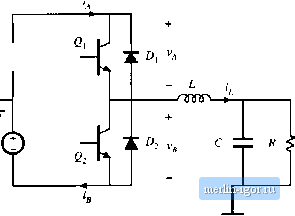 D{0=0.5 + D ,siit(()WJ (4,2) witii being a constant less that 0.5, the output vttltage beeomes sinusoidal. Hence tiiis converter could i)e used as a dc-ac inverter. The load current is given by vR\ in equilibrium, this current coincides with the inductor current (4.3) The switches must conduct this ctirrent. So the switch current is also positive when D > 0.5, and negative when D < 0.5. With high-frequency duty cycle variations, the L-C filter may introduce a phase lag into the inductor current waveform, but it is nonetheless true that switch currents of both polarities occur. So the switch must operate in two quadrants of the plane, as illustrated in Fig. 4.13. When i, is positive, £)[ and Dj alternately conduct. When i[ is negative, and D, alternately conduct. A well-known dc-30ac inverter circuit, the voltati-.source inverter (VSl), operates in a similar manner. As illustrated in Fig. 4.14, the VSI contains three two-quadrant SPDT switches, one per phase. These switches block the dc input voltage V, and must conduct the output ac phase currents i i and i., Fig. 4.12 Output voltage vs. duty cycle, for the tiivectcr of Fig. 4,11, Iliis converter can produce both positive and negative output voltages, 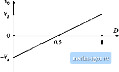 |