
|
| |
|
Строительный блокнот Introduction to electronics Fig. 18.40 Switch waveforms, 3fiac-dc boost rectifier. Cotuiuciing i*... /0, -i-devices: ; 1-Gj/ {t)),-d,u){m), The averaged line-to-iine switch voltages are therefore {v 0))r, = (i3o(0),- (v, (f)), = [,(f) - d,{t)] {vi!)) (18.153) (1Б.154) In a similar manner, the average switch currents can be shown to be (1S.155) Equations (18.154) and (18.155) lead to Ihe circuit-averaged model of Fig. 18.41. With sinusoidal PWM, the duty cycles are varied sinusoidally in synchronism with the ac line, as follows: (/,(() = Oo + i£> , sin (oir-ip) tliit) = D + i D sin (wf - Ф - 120°) dil) = t i P sin (cw - <p - 340 (18,156) where tt) is the ac line frequency. Since each instantaneous duty cycle must lie in the interval [0,1], the dc bias Z>( is required. The factorD is called the modukilion index: forD = 0.5, D , must be less than or equal to one. Other choices of Z) further restrict In general, the modulation index can be defined as equal to the peak-to-peali amplitude of Ihe fundamental component of the duty cycle variation. If the switching frequency is sufficiently large, then filter inductors i can be small in value, such that they have negligible effect on the low-frequency ac waveforms. The averaged switch voliage (Vj2(r))j, then becomes approximately equal to Ihe ac line-line voltage Vjj,(f): (v (0), = (,(f)-2(0){*)) = v ,(t) Substitution of Eqs. (18.150) and (18.156) leads lo sin(w-<p)-siii(o)f-(f>-120P] {v(())r=l sin (шг)-sin (u)/-120°) (ia,157) (18,158) For small L. the angle <p must tend to zero, and hence Ihe sinusoidal terms in Eq. (18.158) cancel otii. In steady-state, Ihe dc output voltage is {v(f)) = V. Equation (18.158) Ihen becomes Solution for the dc output voltage V leads to (18.139) 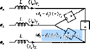 Load Fig, 18.41 Averaged model of ihe open-loop Saac-dc boost rectifier. Fiihe-Widrk Modulated Rectifiers Equation (18.160) can be written in terms of the peak line-to-litie voltage Vf. ), /i D , D (I K.I 60) (18,161) With < 1, the dc outpitt voltage V must be greater than or eqtial to 1.15 times the peak line-to-line ac input voltage. Thus, the rectifier has a boost characteristic. The sinusoidal PWM approach ofEq. (18.156) i.s not the only way to vary the duty cycles to obtain sinusoidal ac voltages and currents. For example, triplen harmonics can be added to the duty cycle expressions of Eq. (18.156). These triplen harmonics cancel out in Eq. (18.154), .such that the average inverter input voltages {viO, {v2jf())j, and (vjj(f)) contain only fundamental. Figure 18.42 illustrates duty cycle variations that lead to a dc output voltage Vequal to V.The effective modulation index in this case is 1.15. The ac-side voltages and curretiLs are again undistorted. Funher increases in the modulation index can be attained only by imroditction of distortion in the ac-side voltages and currents. Of course, in practice the duty cycle modulations are usually generated by the feedback loops that control the input currettt waveforms to attain resistor emttlation. Three-phase ac-to-dc rectifiers having buck, buck-boost, or other characteristics, are possible, btti find mttch less use thati the boost topology. A 30ac-dc recdfier system can also be cotistrttcted simply using three separate single-phase rectifiers [34]; however, each single-phase rectifier must then contain transformer isolation, leading to substantially increased swiich stress and loss. Other unconventional approaches to three-phase low-harmonic rectification have also been recently explored, such as the Vienna rectifier [56,59], single-switch approaches [49-55], and other circttits[44,45,46,57,58]. Yet another approach to solving the problem of three-phase rectifier harmonics is the harmonic correction scheme illustrated in Fig. 18.43. An acdve six-switch three-phase bridge removes the harmonics generated by a nonlinear three-phase load such as an uncontrolled rectifier. The harmonic corrector is controlled sttch that its ac Une currents contain harmonics that are equal in magnitude but opposite in phase to the harmonics generated by the tionlinear load. No average power flows into the harmonic corrector. The total kVA rating of the harmotiic corrector semicotidttctor devices depends on the magnitttdes of the harmonics produced by the tionlinear load. If the THD generated by the load is not too large, then Fig, 1Я,42 л muduia-tion strnreey thai leads to a dc outiiut voltage equal lO the peak input line-line voltage. 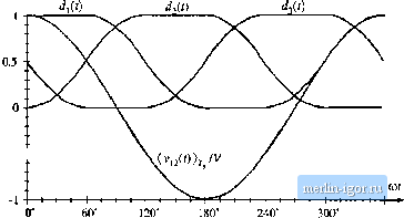 -0.5 -- |