
|
| |
|
Строительный блокнот Introduction to electronics dc source тлпг1-1- Switch network (c) r- Resistive CpZpi m f load R Resonant tardc network ......................1 m r- Series tank network Parallel tatjk network LCC tank network Fijj. 19.1 A biisic class of resonant inveiters that consist of (a) a switcit network Л that drives a re.sonant tank network iVj.near resonance. Several common tank networks: (b) series, (c) pai-aliel, (d) LCC. Fig, 19,2 The tank network responds primarily to the fiiiidanieiital coinponent of the applied waveforms. Switch output voltage spectmm Resonant tank response Tank current spectrum 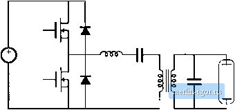 Pig. 19,3 Half-bridge LCC inverter ciiruit;, а.ч un electronic ballast for a gas-diacharge lamp. Transfer Junction 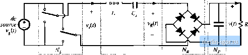 1 Kt) fr...............I I................ Switch network Resonant tank network Rectifier network Low-pass dc filter load network Fig. 19.4 Deiivution (if a resonant dc-dc converter, by rectification and filtering of the output of a rcsoiianl inverter. high-frequency ac vi-aveform. Tlie conveiter is contruiied tu provide a relatively high voltage to start the lamp, and a lower voltage thereafter. Wlien the ballast is powered by the ac utility, a iow-harmcmic rectifier typically provides the input dc voltage for the inverter. A resonant dc~dc converter can be constructed by rectifying and filtering the ac outptit of a resonant inverter. Figure 19.4 illustrates a series-resonant dc-dc converter, in which the approximately sinusoidal resonant tank output current iff(t) is rectified by a diode bridge rectifier, and filtered by a large capacitor to supply a dc load having ctirrent / and voltage V. Again, by variation of the switching frequency / (closer to or further from the resonant frequency /д), the inagnitude of the tank current !(f), and hence а1.чо die dc load current /, can be controlled. Resonant dc~dc converters based on series, parallel, LCC, and other resonant tanlt networlts are well understood. These converters are employed when specialized application requirements justify their use. Forexample, they are cominonly employed in high voltage dc power supplies [5,6], because the substantial lealtage inductance and winding capacitance of high-voltage transformers leads unavoidably to a resonant tanlt network. The same principle can be employed to construct resonant lii± inverters or resonant linlt cycloconverters [7-9]; controllable switch networlts are then employed on both sides ofthe resonant tanlt networlt. Figure 19.5 illustrates another approach to resonant power conversion, in which resonant ele- PWM switch network ZCS quasi-resonant Sivitck network
T 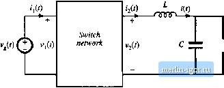 R г v(t) Fig. 19.5 Cterivation of я cjuasi-resonant conveiter: (a) conventional PWM swiich iiecwork, (b) a ZCS quasi-reso-tiant switcli network, (e) a uasi-resonant buck converter is obtained by employing a quasi-resonant switch network such as (b) in a buck convurtcr. ments are inserteti into the switch network of an otherwi.se-PWM converter. A resonant swiich network, or quasi-resonam converter, is then obtained. For example, in Fig. 19.5(h), resonant elements and are combined with the switch network transistor and diode. The resonant frequency of these elements is somewhat higher than the switching frequency. This causes the switch network waveforms ij{r) and Vj(() to become quasi-sinusoidal pulses. The resonant switch network of Fig. 19.5(b) can replace the PWM switch network of Fig. 19.5(a) in nearly any PWM converter. For example, insertion of the resonant switch network of Fig. 19.5(b) into the converter circuit of Fig. 19.5(c) leads to a quasi-resonant buck converter Numerous resonant switch networks are known, which lead to a large number of resonant switch versions of buck, boost, buck-boost, and other converters. Quasi-resonant converters are described in Chapter 20. The chief advantage of resonant converters is their reduced switching loss, via mechanisms known as zero-current switching (ZCS), and z.ero-whafe switciiing (ZVS). The turn-on antl/or turn-off transitions of ihe various converter semiconductor elements can occur at zero crossings of the resonant converter quasi-sinusoidal waveforms. This eliminates some of the switching loss mechanisms described in Chapter 4. Hence, switching loss is reduced, and resonant converters can operate at switching frequencies that are higher than in comparable PWM converters. Zero-voltage switching can also eliminate some of the sources of converter-generated electromagnetic interference. Resonant converters exhibit several disadvantages. Although the resonant element values can be chosen such that good performance with high efficiency is obtained at a single operating point, typically it is difficult to optimize the resonant elements such that good performance is obtained over a wide range of load currents and input voltages. Significant currents may circulate through the tank elements, even when the load is removed, leading to poor efficiency at light load. Also, the quasi-sinusoidal waveforms of resonant converters exhibit greater peak values than those exhibited by the rectangular waveforms of PWM converters, provided that the PWM current spikes due to diode stored charge are ignored. For |