
|
| |
|
Строительный блокнот Introduction to electronics these reasons, resonant converters exhibit increaseiJ continction losses, which can offset their reduced sv/itching losses. In this chapter, the properties ofthe series, parallel, and other resonant inverters and dc-dc converters are investigated using the sinusoidal approximation [3, 10-12]. Harmonics ofthe switching frequency are neglected, and the tanlt waveforms are assumed to be purely sinusoidal. This allows simple equivalent circuits to be derived for the bridge inverter, tank, rectifier, and output filter portions of the converler, whose operation can be understood and solved using standard linear ac analysis. This intuitive approach is quite accurate for operation in the continuous conduction mode with a high- response, but ijecomes less accurate when the tanlt is operated with a low -factor or for operation of dc-dc resonant converters in or near the discontinuous condticlion mtKle. For dc-dc resonant converters, the important result of this approach is that the dc voltage conversion ratio of a continuous condttction mode resonant converter is given approximately by the ac transfer function of the tanlt circuit, evaluated at the switching frequency. The tank is loaded by an effective output resistance, having a valtie nearly equal to the output voltage divided by the output current. It is thtis quite easy to detemiine how the tank components and circuit connections affect the converter behavior. The influence of tank component losses, transformer nonidealities, etc., on the output voltage and converter efficiency can also be found. Several resonant networlt theorems are presented, v/hich allow the load dependence of conduction loss and of the гего-voiiage- or гего-current-switching properties to be explained in a siinple and inttiitive manner. It is found that the series resonant converter operates with a step-down voltage conversion ratio. With a 1:1 transformer ttirns ratio, the dc output voltage is ideally equal to the dc input voltage when the transistor switching frequency is equal to the tank resonant frequency. The otitput voltage is reduced as the switching frequency is increased or decreased away from resonance. On the other hand, the parallel resonant converter is capable of both step-tip and step-down of voltage levels, depending on the switching frequency and the effective tanlt £l-factor. The exact steady-state solutions of ihe ideal series and parallel resonant dc-dc converters are stated in Section 19.5. Zero-voltage switching and zero-current switching mechanisms ofthe series resonant converter are described in Section 19.3. In Section 19.4, the dependence of resonant inverter properties on load is examined. A simple frequency-domain approach explains why some resonant converters, over certain ranges of operating points, exhibit large circularing tanlt currents and low efficiency. The boundaries of zero-voltage switching and zero-current switching are also determined. It is also possible to modify the PWM converters of the previous chapters, so that zero-current or zero-voltage switching is obtained. A number of diverse approaches are known that lead to soft switching ill buck, boost, forward, flyback, bridge, and other topologies. Chapter 20 stimmarizes some ofthe weli-ltnown schemes, including resonant switches, quasi-square wave switches, the full-bridge zero-volt-age transition conveiter, and zero-voltage switching in forward and flyback conveiters contnining active-ciainp snubbers. A detailed description of soft-switching mechanisms td diodes, MOSFETs, and IGBTs is also given. 19.1 SINUSOIDAL ANALYSIS OF RESOINAINT CONVERTERS Consider the class of resonant converters that contain a controlled switch network that drives a linear resonant tanlt networlt Л,-, In a resonant inverter, the tank network drives a resistive load as in Fig. 19.1. The reactive component ofthe load impedance, if any, can be effectively incoфorated into the tank network. In ihe case of a resonant dc-dc converter, the resonant tank neiwork is connected to an uncontrolled rectifier network Af, filter network and load R, as illustrated in Fig. 19.4. Many well-known converters can be represented in this form, including the series, parallel, and LCC topologies. In ihe most eoininon modes of operation, the eontrolled switch network produces a square wave voltage output vj.1) whose frequency/, is close to the tank network resonant frequency,- In response, the tank network rings with approximately sinusoidal waveforras of frequency/. In the case where the resonani tank responds primarily to the fundamental component/of the switch waveform v,(r), and has negligible response at the hannmiic frequencies nf, и = 3, 5, 7,..., then the tank waveforms are well approximated by their fundamental components. As shown in Fig. 19.2, this is indeed the case when the tank network contains a high-g resonance at or near the switching frequency, and a low-pass characteristic at higher frequencies. Hence, let us neglect harraonics, and corapute the relationships between the fundamental components of the tank terminal waveforms i,(r), (\(f). t n- 19.1.1 Controlleti Switch Network Model If the switch network of Fig. 19.6 is controlled to produce a square wave of frequency/, = ti)/2n as in Fig. 19.7, then its output voltage wavefurmVj(f) can be expressed in ihe Fourier series v,(0 = - 2 /i sin Uiiaj) The fundamental coinponent is vji)-. sin U,}J}= (td.I) (ly.l) 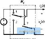 Switch network Ilg. 19.6 An idcid switch network. which has a peak amplitude of (4/л) times the dc input voltage Vj and is in phase vrith the original square wavei/O- Hence, the switch network output terminal is modeled as a sinusoidal voltage generator, .yiit). It is also of interest to inodel the converter dc input port. This requires computation of the dc component ! of the switch mput current !,((). The switch input current !,(() is equal to the output current !,(f) when the switches are in position 1, and its inverse - i(() when the switches are in position 2. Under the conditions described above, the tank rings sinusoidally and iJt) is well approximated hy a sinusoid of some peak amplitude /,[ and phase Cp,: i-,ft) = i sin(m,f-(p,) (19,3) Kig. 19.7 Switch network outpui voltage vft) and its fuirdaiiiental component v,(r). Fundamental component 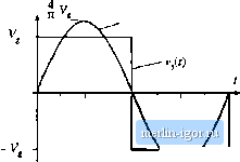 Fig, 19.8 Switch network wiiveforms i,(0 and (.(0. 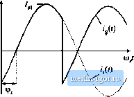 sin (M) sin ((HJ-tf),) Fig. 19.9 An equivalent circuit for the switch network, which models the fundamental component of the output voltage waveforin and the dc component of the input current waveform. The input current waveform is shown in Fig. 19.8. The dc component, от average value, of the input current can be found by averaging i(f) over one half switching period: -f- /,1 а;п(а>,г-ф,)(;т i Jii (19.4) Thus, the dc component ofthe converter input current depends directly on the peak amplitude ofthe tanlt inputcurrent /jiUnd on the cosine of its phaseshifHf,. An equivalent circuit for the switch is given in Fig. 19.9. This circuit tnodeis the basic energy conversion properties of the switch: the dc power supplied by the voltage source V, is converted into ac power at the switch output. Note that the dc power at the source is the product ot and the dc component of ijj(0, and the ac power at the switch is the average of v/f)iffl Furthermore, if the harmonics of Vj(f) are negligible, then the switch output voltage can be represented by its fimdaraental component, a sinusoid Vji{f) of peak amplitude4V/jt. It can be verified that the switch network dc input power and fundamental average output power, predicted by Fig. 19.9, are equal. 19.1.2 Modeling the Rectifier and Capacitive Filter Networks In the series resonant dc-dc converter, the output rectifier is driven by the nearly sinusoidal tanlc output current <д(()-A large capacitor C.. is placed at the dc output, so that the output voltage i(r) contains negh-gible harmonics of the switching frequencyas shown in Fig. 19.10. Hence, we can make the small-rip- |