
|
| |
|
Строительный блокнот Introduction to electronics Pig. 19.1(( Uncoiuroiled rectifier witti capacitive filter network, as in tiie series resonant converter. 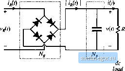 Reciifier network Low-pass filter network pie approximation as usual: v(t) = V, i(t) = /. The diode rectifiers switch when ifit) passes through zero, as shown in Fig. 19.11. The rectifier input voltage V/j(t) is essentially a square wave, equal to + i(r) when ijf(t) is positive and - v(f) when ijW is negative. Note that Vjij(() is in phase with i((). If the tank output current if.(t) is a sinusoid with peakamplitiide Ij and phase shift ф; !нС0 = /л1 sin К/-<Рд) then the rectifier input voltage may be expressed in the Fourier series l (f) = I sill (Al(U/ - ф ) (19.5) (1У.6) where фfis the phase shift of ijj(()twith respect to vt)-This voltage waveform is impressed on the output port of the resonant tank network. Again, if the tank network responds primarily to the fundamental component (/,.) ofV/t), and has negligible response at the harmonic frequencies tl/., n = 3, 5, 7..., then the harmonics of vCO can be ignored. The voltage waveform Vg(() is then well approximated by its fundamental component v,n{t) = s\a(U)j-(fK)=Vg, sill ((о.г-фд) (19.7) The fundamental voltage component v,(f) has a peak value of (4/3l) times the dc output voltage V, and is in phase with the current J(0. 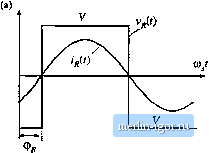 fimdammtal 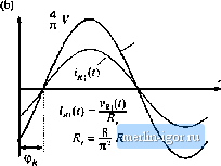 Fig. 19.11 Rectifier network input terminal waveforms; (a) actual waveforms v(0 and r((), (b) fundamental components v(r) and ij ((). Fig. 19.12 An equivalent circuit for the rectifier and filter network, which models the fundametiial components of the rectifier ac iitptJt wavefornns and the dc cornponents of the load waveforms. The rectifier presents an effective resisdve load Д to the tank network. The rectified tank output current, ip(f) , is filtered by capacitor C. Since no dc current can pass through Cp, the dc component of ((0 must be equal to the steady-state load current /. By equating dc components we obtain: (19.8) Therefore, the load current and the tank output current amplitudes are directly related in steady state. Since Vjff(t), the fundamental component oiVg(t), is in phase with the rectifier presents an effective resistive load R, to the tank circuit. The value of Я, is equal to the ratio of Vg(l) to ifit). Division ofEq. (19.7) by Eq. (19.5), and elimination of/, using Eq. (19.8) yields i (f) I With a resistive load R equal to V/I, this equation reduces to (W.9) (19.10) Thus, the tank network is damped by an effective load resistance R equal to 81% of the actual load resistance R. An equivalent circuit that models the rectifier network input port fundamental components and output port dc comptments is given in Fig. 19.12. 19.1.3 Resonant Tank Network We have postulated that the effects of harmonics can be neglected, and we have consequently shown that the bridge can be modeled as a fundatnental voltage source Vjf). In the case of a dc-dc converter, the rectifier can be mtxleled using an effective resistor of value R. We can now solve the resonant tank network by standard linear analysis. As shown in Fig. 19.13, the tank circuit is a linear network with the following voltage transfer function: Hence, the ratio Vj/V,! of the peak magnitudes of VfliCO and v,[(r) is given by: In addition, t (i) is given by: So tlie peak magnitude of i(0 is: (1Q.12) mil) Trail s/er fimction H(s) i(f> Resonant network Fig. 1У.13 The linear tank network, excited by an (iy,l4) effective sinusoidal input source and driving an cffee-five resistive load. --RT- Thus, the magnitude of the tank transfer function is found, with an effective resistive load. 19.1.4 Solution of Converter Voltage Conversion Ratio M = V/V An equivalent circuit of a complete dc-dc resonant converler is depicted in Fig, 19.14. The voltage conversion ratio of the resonant converter can tiow be found: (19.15) Simplification by use ofEq. (19.10) yields; Transferfunction ms) 1 / -JT sin t /> Resonant network 1(0 Fig. 19.14 Slcady-stiite equivalent circuit that models the dc and fuiidameiilal compuntnts of resonant converter waveforms. |
|||||||||||||||