 | |
|
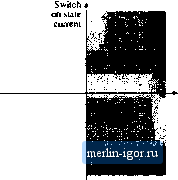
Строительный блокнот Introduction to electronics Fig. 4.13 Ъc switches in the iiivertei of Fig. 4.11 must be capable of conducting both positive and tiiigative curretit, t)ut need block only positive voltage.  Switch off state voltage  Fig. 4.14 The dc-30ae vojtage-.soyi-ce inveitec requires iwo4juadrant .switches, respectively. Atiother ciirretit-biditecttonal two-quadrant switch example is the bidirectional battery charger/di.scharger illustrated in Fig. 4.i5. This converter can be u.sed, for exatnpie, to interface a battery to the main power bus of a .spacecraft. Both the dt bus voltage v,. and the battery voitage are always positive. The semicotiductor switch elenietits block po.sitive voltage Vy, ,.. When the battery is being charged, i, is positive, and atid Dj altertiately conduct current. When the battery is being discharged, ii is negative, and atid alternately conduct. Although thi.s is a dc~dc converter, it require.s two-quadrant .switches because the power can flow in either direction. to. Spacecraft main power bus Fig. 4.15 Bidirectional btuiery chaiger/discharger, based on the dc-dc buck eonvertec. Switch on stale current Fig. 4.16 Voltage-bidirectional two-quadram switch pLopeities.  Switch off stile voluge Fig. 4.17 A voltage-bidirectional two-cjuad-rant SPST switch: (a) implementation using a transfstor and series diode, (b) Idealized switch characteristics.
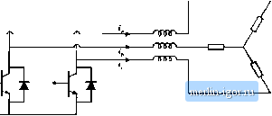
4.1.3 Vultage-Bidirectiunal Two-Quudrant Switches Another type of two-t]iiadrant switch, having the voltage-bidirectional properties illustrated in Fig. 4.16, is sometimes required. In applications where the switches must bloclt btrth positive and negative voltages, but conduct only positive current, an SPST switch can be constructed using a series-connected transistor and diode as in Fig. 4.17. When it is intended that the switch be in the off state, the controller turns the transistor off. The diode then blocks negative vt)ltage, and the transistor bitjcks positive voltage. The series connection can block negative voltages up to the dit)de voltage rating, and positive voltages up to the transistor voltage rating. The silicon-controlled rectifier is another example of a voltage-bidirectional two-quadrant switch. A converter that requires this type of two-quadrant switch is the dc-3fiac buck-boost inverter shown in Fig. 4.18 [4]. If the converter functit)ns in inverter mode, so that the inductt)r current ;,(f) is always positive, then all switches conduct only positive current. But the switches must block the tnitput ac line-to-line voltages, which are sometimes positive and stmetimes negative. Hence voltage-bidirectional two-quadrant switches are required. Fig. 4.18 Di;-30nt; buck-boost inverter. 4.1.4 Four-Quudrunl Switches .ДО The most general type of switch is the four-quadrant switch, Swiich capable of conducting currents of either polarity and blocking voltages of either polarity, as in Fig. 4.19. There are several ways of constructing a four-quadrant switch. As illustrated in Fig. 4.20(b), two current-bidirectional two-quadrant switches described in Section 4.1.2 can be connected batk-to-back. The transistors are driven on and off simultaneously. Another approach is the antiparallel connection of two voltage-bidirectional two-quadrant switches described in Section 4.1.3, as in Fig. 4.2()(a). A third approach, using only one transistor but additional diodes, is given in Fig. 4.2()(c). Cycloctjnverters are a class of converters requiring ft) ur-quad rant switches. For example, a 3dac-to-3(iac matrix converter is illustrated in Fig. 4.21. Each t)f the nine SPST F1& l* A four-quadrant switch can con-switches is realized using one of the seiniconductor networks P*У of Fig. 4.20. With proper control of the switches, this con- enber polarity of voltage, verter can produce a three-phase output of variable fre-
Fig. 4.20 Three ways of implementing a four-quadraiit SPST swiich. (b) 1  |