
|
| |
|
Строительный блокнот Introduction to electronics Transfer function His) Fig. 19.30 Resonant inverter nnodel. Effective sinusoidal source Resonant network Purely reactive Effective > resistive To (Jesign a resonant converter that exhibits gotxi properties, the engineer must (Jevelop physical insight into how the load resistance R affects the tank input impedance and output voltage. In this section, the inverter output characteristics, zero-voitage switching boundary, and the dependence of transistor current on load resistance, are related to the properties of the tank network under the extreme conditions of an open-circuited or short-circuited load. The undatnped tank network responses are easily plotted, and the insight needed to optimize the tank network design can be gained quickly. 19.4.1 Inverter Output Characteristics Let us first investigate how the magnitude ofthe inverter output voltage v depends on the load current magnitude /1, Consider the resonant inverter systetn of Fig. 1930, Let Cj) be the open-circuit (R So) tran.sfer function ofthe tank network: HJs) = vis) (19.33) and let Zis) be the output impedance, determined when the source Vj.,(.v} is short-circuited. Then we can model the output port ofthe tank network using the Thevenin-equivalent circuit of Fig. 19.31. Solution □f this circuit using the voltage divider formula leads to m = HJs)v,i(s) PrZJs} (19.34) At agiven angular switching frequency = 2л/, the phasor representing the magnitude and phase of the ac output voltage is found by letting j =j<i)j; vOJ = (jtu,)v 0 ) - (19.35) + 2(7W,) The magnitude tan be found by noting that v0a),)j = vO4)v*(MJ (-36) where С/Ш,) is the complex conjugate of v(ju)J. Substitution ofEq. (19.35) into Eq. (19.36) leads to 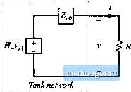 I1g, 19.31 Thevenln-equtvalcnt circuit that modcts the output port of the tank network. R + ZJjui,) = \HjM)f\v,0,)\ R + ZJjm,) (19.37) Ttiis result can be further sitnplified with the assumption that the tank network contains only purely reactive elements, i.e., that any losses or other resistive elements within the tank network have negiigibie effect. Then the output impedance Z(j(ii), as well as all other driving-point impedances of the tank network, are purely imaginary quantities. This implies that the complex conjugate Z(J(ii) is given by Substitution ofEq. (19.38) tntoEq. (19.37) and simplification leads to (19.38) v(j-a)J - г,<,(М)Г (19.39) with (M) Substitution ofEq. (19.40) into Eq. (19.39) and rearrangement of terms yields I v(M.) + II iOa),))z o04} = I (М)Г У.Ш I (19,40) (19.41) Hence, at a given frequency, the inverter output characteristic, that is, the relationship between Ц vOCJj) I and II JC/I,) II, is elliptical. Equation (19.41) can be further rearranged, into the form * 1 Fie. 1?32 E)lip(ical oulpul tharacleristics of resonant inverters. A resistive matched bad if al;>o illustrated.
llvll where tlie open-circuit voltage V] . and short-circuit current are given by (19.42) (19.43) These inverter output characteristics iue constructed in Fig. 19.32. This characteristic describes how, at a given switching frequency, the ac output voltage magnitude varies as the circuit is loaded. The equilibrium output voltage is given by the intersection of this elliptical characteristic with the load i-i characteristic. For exatnple. Fig. 19.32 also illustrates a superimposed resistive load line having sltipe l/R. in the special case where R-\\ 2(Js) 11-This value of R corresponds to matched load operation, in which the converter output power is maximized. It can be shown that the operating point is then given by (19.44) Note that Fig. 19.32 can а1.чо be applied to the output I-v characteristics of resonant dc-dc converters, since the output rectifier then loads the tanlt with an effective resistive load H- 19.4.2 Dependence tif Transistor Current on Load The transistors must conduct the current appearing at the inpnt pott of the tanlt network, i,(/). This current is determined by the tank network input itnpedance 2-(Уш): |