
|
| |
|
Строительный блокнот Introduction to electronics Fig. 19.35 Construction of the quantities \\Zj\\ [Zi ,forthe LCC inverter. Fig. 1936 Variation of tank network input impedance IIZ, II with load resistance R, LCC irverter. As the load resistance is increased, Z, changes monotonically from IIZ,.(,1WZ, . 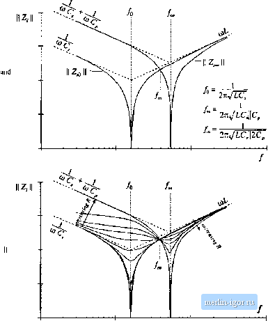 If the switching frequency is chosen to be greater than/ then jl Zf is less than HZnH-This itnplies that, as the load current is decreased, the transistor current will increase. Such a converter will have poor efficiency at light load, and will exhibit significant circulating currents. If the switching frequency is chosen to be less thanthen the transistor current will increase with decrease with decreasing load current. The short-circuit current is limited by II Z.g , while the circulating currents under open-circuit conditions are determined by Zj \\. In general, if/>/, then the transistor current is greater than or equal to the short-circuit current for all R. The inequality is reversed when/</, . The impedance magnitudes Z and are illustrated in Fig. 19.34 for the series, parallel, and LCC tank networks. In the case ofthe series tank network, Z; In consequence, the no-load transistor current is zero, both above resonance and below resonance. Hence, the series resonant inverter exhibits the desirable property that the transistor current is proportional to the load current. In addition, when the load is short-circuited, the current magnitude is limited by the impedance ofthe series resonant tank, Forthe parallel and LCC inverters, it is desirable to operate below the frequency/. Thus, the dependence ofthe transistor current on load can be easily determined, using an intuitive frequency-domain approach. 19.4.3 Dependence of the ZVS/ZCS Boundary un Luad Resistance h is also necessary to determine the critical load resistance R = /f. , at the boundary between ZVS and ZCS. This boundary can also be expressed as a function of the impedances Zj, and Z; . As discussed in Section 19.3, zero-voltage switching occurs when the switch current (,(() lags the switch voltage vii). Zero-voltage switching occurs when i[t) leads v,(;). This definition ignores the effects of semiconductor outptit capacitances, and hence gives an approximate ZVS/ZCS boundary. The phase between the switch current and switch voltage is again determined hy the input impedance of the tank network: (19.53) Hence, zero-voltage switching occurs when Zfjm) is inductive in nature, zero-current switching occurs when ZjC/W,.) is capacitive in nature, and the ZVS/ZCS boundary occurs where Zjus) has zero phase. It is instructive to again consider the limiting cases of a short-circuited and open-circuited load. The Btxle plots ofZy(,OC>j) andZ.Д/alJ.) for an LCC inverter example are sketched in Fig. 19.37. Since, in these limiting cases, the input impedance Z. is composed only of the reactive tank elements, Z-ijiii) and 2(jtu,) are purely imaginary i]uantities having phase of either - 9()° or + 9(F. For /j </(). both Zj(J(Si) and Z- (jCUj) are dominated by the tank capacitor or capacitors; the phase ofZj(jCU,.) is therefore -90°. Hence, zero-current switching is obtained under both short-circuit and open-circuit conditions. For / >both Z,(j(/lOj) and Zj (ju)j) are dominated by the tank inductor; hence the phase ufZfjtii) is + 90 . Zero-voltage switching is obtained for both a short-circuited and an open-circuited load. For</ , Z;()(jtu,) is dominated by the tank inductor while Z,{j(i)J is dominated by the tank capacitors. This implies that zero-voltage switching is obtained under short-circuit conditions, and zero-voltage switching is obtained under open-circuit conditions. For this case, there must be some critical value of load resistance R = й;, that represents the boundary between ZVS and ZCS, and that causes the phase of Ziifdi,) to be equal to 0°. The behavior of Zj(jCflj) for nonzero finite R is easily extrapolated from the limiting cases dis- F[g. 19,37 Use of the input impedance quantities Zg and 2j to determine the ZCS/ZVS boundaries, LCC example. 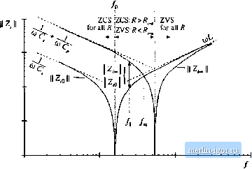 cussed above. Theorem 2 below shows that: 1, Itzero-CLUTent switching occurs for both an open-circuited load and a short-circuited load [i.e., Z.j(jtii) and Z( (j(t)j) both have phase + yO°J, then lero-carreiit switching occurs for all loads. If zero-volLage switching occurs for boLh an open-circuited load and a stiorl-cirCLiited load [i.e., Z.ijiii} and ZijbiJ both have phase - then zero-voltage switching occurs for all loads. If zero-voltage switching occurs for an open-circuited load and zero-currenl switching occars fora short-circuited load [i.e., has phase - 90° and ZJJw) has phase + 9Uj, then гего-vollage swiLchiiig occars for К > К and zero-carrent switching occurs for with given by Eq. (19.54) below. If zero-carrent switching occurs for an open-circuited load and zero-voltage switching occars for a shon-circLiited load [i.e., Z(Jin) has phase + 90 and ZfOi) has phase - 9Uj, then zero-carrent switching occars for RPfn,. and zero-vohage switching occurs for ;.,jv> with given by Eq. (19.54) below. For the LCC example, we can therefore conclude that, for/, <yj zero-cnrrent switching occurs for all values of R. For/ zero-voltage switching occurs for ail values of R. For /q </, <f , the boundary between ZVS and ZCS is given by Eq. (19.54). Theorem 2: If the tank network is purely reactive, then the boundary between zero-current switching and zero-voitage switching Mcurs when the load resistance Л is equal to the critical value fi , given by (19,54) This theorem relies on the assumption that zero-current switching occurs when the tank input itnpedance is capacitive in nature, while zero-voitage switching occurs for inductive input impedances. The boundary therefore occurs where the phase ofZ,(/w) is zero.Thisdefinition givesanecessary biitnotsufficient condition for zero-voitage switching when significant setniconductor output capacitance is present. The result is derived by finding the value of Л which causes the imaginary part oiZ-iJui) in Eq. (19.47) to be zero. Since the tank network is assumed to ideal and lossless, the impedances Zj,. , Z, and Z must have zero real parts. Hence, lm(Zi(ff, ,)] = 4z,J Re (19.55) where Im(Z) and Re(Z) denote the itnaginary and real parts ofthe cotnpiex quantity Z. The nontrivial solution to Eq. (19.55) is given by 1 =- (19.56) hence. A useful equivalent form makes use ofthe reciprocity identities |