
|
| |
|
Строительный блокнот Introduction to electronics Solution of Eqs. (19.66) and (19.67) for and X, leads to 2(ML (19.63) 1-ffJM) Henee, the eapacitance C, should be chosen equal to X, = - 1493 Д w.A- (DjZ (ja)Jj (2t[ 100 кНг)[ 1439 ii] and the reactance ofthe series branch should be chosen according to ---ralP=(--3.)ii=733. Since Xj. is cotnprised ofthe series combination ofthe inductor L and capacitor C there is a degree of freedom in choosing the values of L and capacitor to realize X,. For example, we could choose C. very large (tending to a short circuit); this effectively would result in a parallel resonant converter with L = = 1.17 tnH. For nonzero C L must be chosen according to (19.71) Forexample, the choice C,. ~ C 1.06 nF leads to L = 3.5 mH. Etesigns using different C, will exhibit exactiy the same characteristics at the design frequency; however, the behavior at other switching frequencies will differ. For the tanlt networlt illustrated in Fig. 19.39, the value of 7Г,; is completely determined by the parameters ofthe output characteristic ellipse; i.e., by the specification of V V, and 1. Note that Z, the tanlt output impedance with the tank input port open-circuited, is equal to . Substitution of expressions for Zjj and Zj(; into Eq. (19.57) leads to the following expression for Л.,-/ / Z?M) (19,72) -\/ 1- (j4) Since Zjjjj and Я are determined by the operating point specifications, then Ri/ is also. Evaluation of Eq. (19.72) for this example leads to - 1466 fi,Therefore, the inverter will operate with zero-voitage switching for R < 1466 il, including at the nominal operating point R = 9(Ю Q. Other topologies of tank networlt, more complex than the circuit illustrated in Fig. 19.39(b), may have additional degrees of freedom that allow Я,.;, to be independently chosen. The choice = 3C= 3.2 nF leads to L = 1.96 H. The following frequencies are obtained: \Z4 X, 733 n 278 A tl-S) which is nearly the same as the result in Eq. (19.75). The somewhat large open-circuit switch current occurs because of the relatively-high specified open-circuit output voltage; lower values of V . would reduce the result in Eq. (19.75). 19.5 EXACT CHARACTERISTICS OF THE SERIES AND PARALLEL RESONANT CONVERTERS The exact steady-state behavior of resonant converters can be determined via methods such as state-plane analysis. A detailed analysis of resonant dc~dc converters is beyond the scope of this book. However, the exact steady-state characteristics of ideal series [1, 13-20] and parallel [6, 22-25] resonant dc-dc converters (Fig. 19.40) are summarized in this section. Small-signal ac modeling has also been described in the literature; several relevant papers are [27-30]. 19.5.1 Series Resonant Converter At a given switching frequency, the series resotiatit dc-dc converter cati operate in one continuous conduction raode, and possibly in several discontinuous conduction raodes. The tnode index к is defined as the integer that satisfies T<4 - kh<l where F = fjffj is the normalized switching frequency. The subharmonic number is defined as / = 127 kHz / = 100.6 кНг j /,= 100.0 kHz a = 64 kHz Regardless of how C, is chosen, the open-tirciut tank input impedance is = jX + ;if ] = j{733 ii + ( - 1493 Й)] = - j760 ii (19.74) Therefore, when the load is open-circuited, the transistor peak current has magnitude When the load is short-circuited, the transistor peak current has magnitude 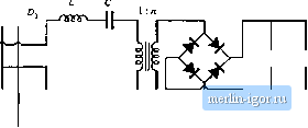 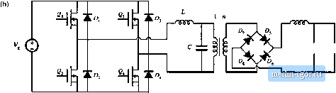 llg. 19.40 Trunsforrnec-isoliited resoniinl dc-dc converters: (a) series le.sonant converter, (b) paiallel rcsoniint cotiverter. {19,78) Values of к and as functions of /, are summarized in Fig, 19.41 (a). The siibharmonic number t, denotes the dominant harmonic that excites the tank resonance. When the converter is heavily loaded, it operates in type к contintious conduction mode. As the load is reduced (i.e., as the load resistance R is increased), the converter enters the type к discontinuous conduction mode. Further reducing the load causes the converter to enter the type(t - 1) DCM, type (jt - 2) DCM..... type 1 DCM. There is no type 0 DCM, and hence when the converter operates above resonance, only ttie type 0 continuous conduction mode is possible. In the type к continuous conduction mode, the series resonant converter exhibits elliptical output ch;iracteristic.4, given by cos (19.79) For the transformer-isolated converters of Fig. 19.40, M and / are related to the load voltage Vand load current / according to V nV. (19.K0) Again, Яц is the tank characteristic impedance, referred to the transformer primary side. The quantity у is the angular length of one-half of the switching period: |