
|
| |
|
Строительный блокнот Introduction to electronics 4 = 3 etc. Jt = 3+rt = 2-.- --i= 1- /о/З /о/2 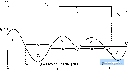  Fig. 19,41 Continuous conduction nradcs of tlio series resoiumt conveiter. (з.\ switciiing li-equeiicy ranges ovei wtiicli variuus mode indicc.-i к and .subharmonic niiintiers 4 occur; (b) tank inductor curreitl waveform, type к CCM. lor odd k\ (c) tank inductor cunent waveform, type к CCM, for siveii k. (19.81) Equation (19.79) is valiil only tort satisfying Eq. (19.77). It preilitts tliat the voltage conversion ratioM is restricted to the range Q<M< (19.S2) This is consistent with Eq. (19.21). Typical CCIVI tank current waveforms are illustrated in Fig. 19.41. When к is even, the tank inductor current is initially negative. In con.sequence, the switch network antiparailel diodes conduct first, for a fraction of a haif resonant cycle. If к is odd, then each half switching period is initiated by conduction of the switch network transistors. In either case, this is followed by - 1) complete tank half-cycles of ringing. The half-switching period is then concluded by a subinterval shorter than one complete resonant half-cycle, in which the device that did not initially condtict is on. The next half switching period then begins, and is symmetrical. The steady-state control-plane characteristic can be found for a resistive load R obeying V= [R, by stibstitution of the normalized relation J - MQ into Eq. (19.79), where Q = nRJR. Use of the quadratic formula and some algebraic manipulations allows solution for M, as a function ofload (via Q) and switching frequency (via Y): (-1) (19.83) This is the closed-form relationship between the conversion ratio M and the switching frequency, for a resistive load. It is valid for any continuous conduction mode k. The type к discontintious conduction modes, for к odd, occur over the frequency range f</ (19.84) In these modes, the output voltage is independent of both load current and switching frequency, and is described by (19.85) The type к discontinuous conduction mode, for odd k, occurs over the range of load currents given by *ti) ,2(- i) (19.86) In the odd discontinuous conduction modes, the tank current rings for к complete resonant half cycles. All four oittput bridge rectifier diodes then become reverse-biased, and the tank current remains at zero until the next switching half-period begins, as illustrated in Fig. 19.42. Series resonant converters are not 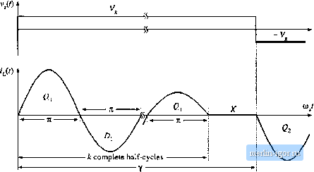 Fig, 19.42 Tank inductor curreitt wnveform, type li DCM, for i)dd k. normally purposely designed to operate in odd discontinuous conduction modes, because tiie output voltage is not controllable. Nonetheless, when the load is removed with/,</[ the series resonant converter operates in i = 1 DCM with M= ]. The type к discontinuous conduction mode, for к even, also occurs over the frequeticy range (19.87) Even discontinuous conduction modes exhibit current source characteristics, in which the load current is a function of switching frequency and input voltage, but not of the load voltage. The output relationship Operation in this mode occurs for 2Jt T (19.88) jt- 1 k+ 1 (19.89) In the even discontinuous conduction modes, the tank current rings for к complete resonant half-cycles during each switching half-period. All four outptit bridge then become reverse-biased, and the tank current remains at zero until the next switching half-period is initiated, Tank current waveforms are illustrated in Fig. 19.43 for even DCM. The series resonant converter possesses some unusual properties when operated in an even discontinuous conduction mode, A dc equivalent circuit is given in Fig. 19.44, consisting of agyrator with gyration conductance g = 2k/gnRy. Tlie gyrator has the property of transforming circuits into their dual networks; in the typical dc-dc convetter application, the input voltage soutce is effectively transformed into its dual, an output current source of value V,. Series resonant converters have been purposely designed to operate in the к - 2 DCM, at power levels of several tens of kW. The complete control plane characteristics can now be plotted using Eqs, (19,77) to (19.89). |