 | |
|
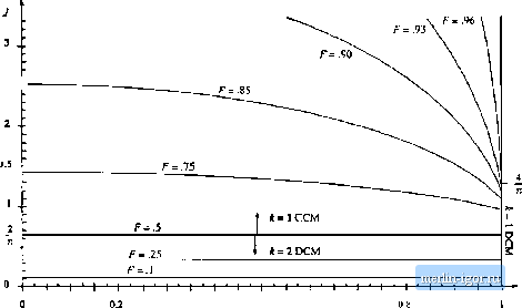
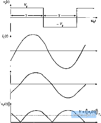
Строительный блокнот Introduction to electronics F= 1.0  0.4 0.6 Fig. 19.48 OLitpui diaractcristics, t. = 1 CCM. к = 1 DCM. and A = 2 DCM (below resonance). 19.5.2 Parallel Resonant Converter For operation in llie frequency range 0,5/g </, < =o, the parallel re.sonant dc~dc converter exhibits one continuous conduction mode and one di.scontinuous conduction mode. Typical CCM switch voltage v,{i), tank inductor current/О), and tank capacitor voltage fO waveforms are iilu.strated in Fig. 19.49. The CCM converler output chatacteri.stics are given by sin (Ф) (19.92)
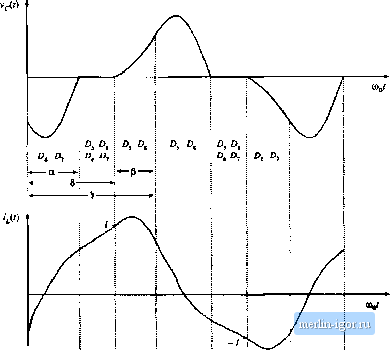
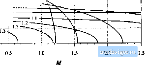
forQ<Y<TC (ubove resonanc;e) for K<y<2n (below EESonance) (19.94) and where M, J. andy are again defined as in Eqs. (19.80) and (19.81). Given the normalized k)ad current } and the half-switching-period-angle Y. one can evaluate Eq. (19.94) to find <p, and then evaluate Eq. (19.93) to find the converter voltage conversion ratio M. In other words, the output voltage can be found for a given load current and switching frequency, without need for computer iteration. Кщ. 19.49 Typical waveforms of the parallel resonant converter, operating in the continuous conduction mode.  A discontintious conduction mode mechanism occurs in the parallel resonant converter which is the dual ofthe discontinuou.4 conduction mode mechanism ofthe series resonant converter. In this mode, a discontinuous subinterval occurs in which all four output bridge rectifier diodes are forward-biased, and the tank capacitor voltage remains at zero. This mode occurs both above and below resonance when the converter is heavily loaded. Typical DCM tank capacitor voltage and inductor current waveforms are illustrated in Fig. 19.50. The condition for operation in the discontinuous conduction mode is y>/ ,(Y) for DCM J<J (Y) for CCM where fy) - - sin (V) + ysiti() + }5Mi(Y] The discontinuous conduction mode is described by the following set of equations: (19.95)  Fig. 19.50 TVpitai waveforms of the parallel resonant converler, operating in the di&coittinuous conductioti mode. 3.0 2.5 2.0 J 1.5 0.5 0.0 .....:.::.-r.r.i0.6 :.i- v..-:s, 0,7 = 0.51 0.Й-j-..........,.i ч -----0-9 -H- 1.0 t  Fig. 19.51 Bxiict output characteristics of tlie parallel resonant converter, for / > 0,5. Solid ciiives: CCM, dashed curves: DCM, |