
|
| |
|
Строительный блокнот Introduction to electronics Transactions on Aerospace and Electronic Systems, Vol. 22, No. 6, pp. 757-763, November 1986. [20] S. Teabert iind R. Erickson, Steady-Siaie Analysis of lhe Duty Cycle Controlled Series Resonant Converter, !EEE Power Electrotiics Specialists Conference, 19Й7 Record, pp. 545-556. [21] K.D.t. Nco, Analysis of a Series Resonant Cunverter Pulsewidth-Modulated of Current-Controlled for Low Switching Loss, IEEE Power Electronics Specialists Conference, 1987 Record, pp. 527-556, June 19S7. [22] R. Orugantf and F.C. Lee, State Plane Analysis of the Parallel Resonant Converter, IEEE Power Electronics Specialists Conference, 19ii5 Record, pp. 56-73, June 19S5. [23] S. JotlNSON, Steady-State Analysis and Design of the Parallel Resonant Converter, M.S. Thesis, University of Colorado, Boulder, 1986. [24] S. Johnson and R. Ericicson, Steady-State Analysis and Design of the Parallel Resoaaat Converter, IEEE Transactions on Power Electronics. Vol. 3, No. 4, pp. 93-104, Jan. 19S8. [25] A. BiLT and M. Swamy, Analysis and Design of a High-Frequency Parallel Resonant Converter Operating Above Resonance, IEEE Transactions on Aerospace and Electronic Systems, Vol. 25, No. 4, July 1989, pp. 449-458. [26] F.S. tsai, P. Materlt, and F.C. Lee, Constant Frequency, Chiraped Mode Resonant Converlers, IEEE Power Electronics Specialists Conference, 1987 Record, pp. 557-566, June 19S7. [27] V. VoRPERlAN and S. tuK, Small-Signal Analysis of Resonant Converters, IEEE Power Electronics Specialists Conference, 19S3 Record, pp. 269-282, June 1983. [28] v. vorperiak, High-2 Appniiimation in the Small-Signal Analysis of Resonant Converters, IEEE Pmver Electronics Specialists Conference, 1985 Record, pp. 707-715, [29] R. King and t. Stuart, Small-Signal Model for the Series Resonant Converter, IEEE Transactions on Aerospace and Electronic Systems. May 1985, Vol. 21, No. 3, pp. 301-319. [30] A. WiTULSK[, A. Hernandh, and R. Erickson, Small-Signal Equivalent Circuit Modeling of Resonant Converters, IEEE Tran.tactions on Power Electronics. January 1991. [31] R. Fi.siiER, K. Nno. and M. Klo, A 500 kHz. 250 W Dc-dc Convener with Multiple Outputs Controlled by Phase-Shifted PWM and Magnetic Amplifiers, / rocffdings of High Frequency Power Conversion Conference, pp. 100-110, May 19S8. [32] L. Mwne, C. WRicnrr, and M. ScuLECiir, A 1 kW, 500 kHz Front-End Converler for a Distributed Power Supply System, IEEE Applied Power Electronics Conference. 1989 Record, pp. 42332. [33] R. Redl, L. Belogh, and D. Edwards, Optimum ZVS Full-Bridge DC/DC Converter with PWM Phase-Shift Control: Analysis, Design Considerations, and Experimental Results, IEEE Applied Power Electronics Conference, 1994 Record, pp. 159-165, [34] J, g. Clio, J, A. Sabate, and F. C. Lee. Novel Full Bridge Zero-Voltage-Transilion PWM DC/DC Converler for High Power Applications, IEEE Applied Power Electronics Conference, 1994 Record, pp. 143-149. [35] О. D. Patterson and D. M. Divan, Pseudo-Resonant Full Bridge DC/DC Converler, IEEE Power Electronics Specialists Conference, WS7 Retord, pp. 424-430. [36] R. F.iERiNOTON, M. JovANOvic, and F. C. Lee, Analysis of Reactive Power in Resonant Converters, IEEE Power Electronics Specialists Cimference, 1992 Record, pp. 197-205. [37] R. D. Middlebrook, Null Double Injection and the Extra Element Theorem. JEEE Transactions on Etiuciition. Vol. 32, No. 3. pp. 167-180, August 1989. [ЗЯ] D. Tltfle. Netivorli Synthesis, New York: John Wiley & Sons, Vol. i, Chapter 6, 1958. Problems 19.1 Analysis of a half-bridge dc-dc parallel resonani converter, operated above resonance. In Fig, 19,53, the elements C , L , and C,. are large in value, and have negligible switching ripple. You may assume that all elements are ideal. You may use the sinusoidal approximatron as appropriate. 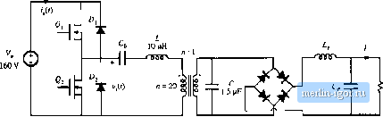 0 o.sr, T, t Fig, 19.53 Half-bridge parallel resonant cunverter of Problem 19,1; (a) schematic, (b) switch voltage waveform. Sketch the waveform of the current;((). Construe tan equivalent circuit for this converter, similar to Fig. 19.22, which models the fundamental components of the tank waveforms and the dc components ofthe converter input current and oulpul voltage. Clearly label the values and/or give expressions for all elements in your model, as appropriate. (c) Solve your model to derive an expression for the conversion ratio VIV - MiF, Q, n). At rated (maximum) load, this converter produces /= 20 A at V= 3.3 V. (d) What is the converter switching frequency /, at rated load? (e) What is the magnittide ofthe peak transistor current at rated load? At imnimum load, the converter produces /= 2 A at V= 3.3 V. (f) What is tlie converter switching frequency f at luiiiimum load? (k) What is the magnitade of the peak transistor current at minimuin load? Compare with your answer from part (e)-what happens to the conductioii loss and efficiency at minimum load? 19.2 A dc-dc resonant converter contains an LCC tank network Hig. I9.1(d)k with an OLitpLit filter contain- ing a filter inductor as in the parallel resonant dc-dc converter. (a) Sketch an equivalent circuit model for Ihis converler, based on the approximate sinusoidal analysis method of Section 19.1, Give expressions for all elements in your model. (b) Solve your mode], to derive an expression for the conversion ratio Л/= V/V. Kxpress Л/ as a function of F-f!f , 2, = RJRa, and n = CJC, where/ is defined as in Eq. (I9.5D) and is LC,C, (t) floe .Vf vs. F, for = I and Q, = I , 2, and 5. (d) Plot M vs. F, for л = t).25 and = 1, 2, and 5. 19.3 Dual nf the series resonant convener In the converter illustrated in Fig. 19.54, tf-p ip2, and are large filter elements, whose switching ripples are small. L and С are tank elements, whose waveforms iil) and Vflt) are nearly sinusoidal. 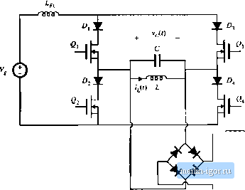 Fig, 19.54 Dual of the series resonant converter, Problein ]y.,l. (a) Using the sinusnidal approximatioii inethod, develop equivalent circuit models for the switch network, tank network, and rectifier network. fb) Sketch a Bode diagram of the parallel LC parallel tank impedance. (c) Solve your model. Find an analytical solution for the converter voltage conversion ratio M= WVj, as a function of the effective and the normalized switching frequency F = JJff,-Sketch M vs. F. (d) What can you say about the validity of lhe sinusoidal approximation for this converter*. iVhich |