
|
| |
Строительный блокнот Introduction to electronics 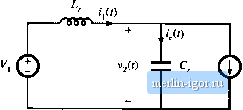 Fig. 20.12 Circuit of the switch network djritig subinterval 2. During subinterval 2, transistor and diode conduct, while diocie fljs reverse-biased. The switch network then becomes the circuit illustrated in Fig. 20.12. The resonant L-C tank network is excited by die constant sources V, and 7. Tlie tietwork equations ate C. = Kri-f, (20.14) with the initial conditions va) = 0 (20.15) The solution is i,(to<ir) = i -l-;Silt(UJnr-Ct) V2(UoO= Il [l - COS (tO(,f - C() The tank inductorcurrent ri.ses to a peiik value given by (20.16) (20.17) The subinterval ends at the first zero crossing of lj(f). If we denote the angular length of the subinterval as p, then we can write Sohition for sin (p) yields (i( -bP) = /j + 4in(p} = 0 (20,18) (20.19) Care must be employed when solving Eq. (20,19) for the angle p. It cau be observed from Fig, 20.10 that the angle P is greater than Jt.The correct branch of the arcsine function must be selected, as follows: P = n + sin (2U.20) 30,2 The Zem-CnrieniSwitching Quasi-Resonant Switch Cell Fig. 20.13 Circuit of the switch network during subinterval 3.  where Note that the inequality -<sin-W< (20.21) mnst be satisfied; otherwise, there is no solnrion to Eq. (20.19). At excessive load currents, where Eq. (20.21) is nt)t satisfied, the tank inductor cjrrent never reaches zero, and the transistor does nt)t switch t)ff at zero current. The tank capacitor voltage at the end of subintervai 2 is found by evaluation ofEq. (20.16) at = (a + P). The cos (P) temi can be expressed as cos (p) = -71 -sin(P) =-Substitution ofEq. (20.22) into Eq. (20.1fi) leads to v,(a + p) = K,i = Vj 1 + ,/VfMa V (20.22) (20.23) At the end of subinterval 2, diode becomes reverse-biased. Transistor can then be switched offal zero current. During subinterval 3, all semiconductor devices are off, and the switch ceil reduces to the circuit of Fig. 20.13. The tank capacitor is discharged by the Filter inductor current Hence, the tank capacitor voltage Vj decreases linearly to zero. The circuit equations are The solution is 12(0; +Ш=,1 (20.24) (20.25) Subintervai 3 ends when the tank capacitor voltage reaches zero. Diode then becomes forward-biased. Hence, we can write where 5 is the angular length of subinterval 3, Solution for 5 yieltis 5 = = (20.27) Subinterval 4, of angular length , is identical to the diode conduclion subinterval of the conventional PWM switch network. Diode conducts the filter inductor cutteiit /j, and the tank capacitor voltage is equal to zero. Transistor Ц[ is off, and the input current ij is equal to zero. The angular length of the switching period is r, = a + P + 5 + t= Y- = x (20.28) where (20.29) Quasi-resonant switch networks are usually controlled by variation of the switching frequency / or, in normalized terms, by variation of F. Note that the interval lengths OL, P, and S are determined by the response of the tank network. Hence, control of the switching frequency is equivalent to control of the fourth subinterval length .The subinterval length must be positive, and hence, the minimum switching period is limited as follows: Substitution of Ec]s. (20.13), (20.20), and (20.27) into Eq. (20.30) yields
(20,31) This exptessitm limits the maximum switching frequency, or maximum F, of the half-wave ZCS quasi-resonaut switch cell. 20.2.2 The Average Terminiil Waveforitbi It is now desired lo solve for the power processing function performed by the switch network. The switch conversion ratio Д is a generalization of the duty cycle d. It expresses how a resonant switch network controls the average voltages and currents of a converter. In our buck converter example, we can define/t as the ratio of {1*2(0)1, to (,(0)7., or equivalently, the ratio of to(/j(t)) . In a hard-switched PWM network, this ratio is equal to the duty cycle d. Hence, analytical results derived for hard-switched PWM converters can be adapted to quasi-resonant converlers, simply by replacing tf with ji. Iu this section, we derive an expression for fx, by averaging the terminal waveforms of the switch network. The switch input current waveform (,(/) of Fig. 20.10 is reproduced in Fig. 20.14. The average switch input current is given by |