
|
| |
|
Строительный блокнот Introduction to electronics [10] R. Redl, В. Mdlnar, iind N. Sokal, Class E Resaniinl Regulated Dc-De Power Converters: Analysis of Operadon and Experimental Results ut 1.5 MHz, JEEE Transaawns on Power Elearonics, 19S6, Vol. 1, No. 2, pp, 111-120. [11] N. Sokal anJ A. Sokal, Class-E, A New Class of High Efficieney TuneJ Single-Ended Switching Power Amplifiers, ;£££JoH;iifi/of ioM Slale Circmis, Vol. SC-IO, June 1975, pp, I6il-I76. [12] F. H. Raab, Idealized Operation of Cla.ss-E Tuned Power Amplifier, JEEE Transacnons on Circuits and Systems, Vol, 24, No. 12, December 1977, pp. 725-735, [13] K. D. T Not). Generalization of Resonani Switches and Quasi-Resonant Dc-Dc Converters, IEEE Power Electronics Specialists Conference, 19S7 Record, pp, 395-403. [14] V. Vorperian, Quasi-Square WaveConverlers: Topologies and Analysis, IEEE Transactions on Power £/ftfronif.!. Vol. 3, No. 2, April 1988, pp, 1*3-191, [15] D. MaXSIMOVIC, Design ofthe Zero-Voltage-Switching Quasi-Square-Wave Resonant Swileh, /£££ Power Electronics Specialists Conference, 1993 Record, pp. 323-329. [16] 0. D. PArrEESo anJ D. M Divak, Pseiido-Resonant Full-Bridge Dc-Dc Converter, f£££ Power Electronics Specialists Conference, 1987 Record, pp. 424-430. [17] Y. Janc; and R. Erickson, New Quasi-Square Wave and Multi-Resonant Integrated Magnetic Zero Vohage Switching Converters, IEEE Power Electronics Specialists Conference, 1993 Record, pp. 721-727. [18] V. Vorperian, R. Tymerski, and F. C. Lee, Equivalent Circuit Models for Resonant and PWM Switches, IEEE Transactions on Power Electronics. Vol. 4, No. 2, April 1989, pp. 205-214. [19] S. Feeeland and R D. Middlebrook, A UnifieJ Analysis of Converters with Resonant Switches , IEEE Power Electronics Specialists Conference. 19S7 Record, pp. 20-30. [20] A. WiTULSKi and R. Erickson, Extension of State-Space Averaging to Resonant Switches-and Beyond, IEEE Traactions on Power Electronics, Vol. 5, No. I, pp. 98-109, January 1990. [21] D. MAK.SlMOVlri and S. CUK, AGeneral Approach lo Synthesis and Analysis of Quasi-ResonantConvert-eis, IEEE Tran.tactiotis on Power Electronics, Vol. 6. No. 1. January 1991, pp. I27-14C. [22] R. Erickson, A. Hernasdez, A. Witulski, and R. Xu, A Nonlinear Resonant Switch, /£££ Transactions on Power Electronics. Vol. 4, No. 2, April 1989, pp. 242-252. [23] 1. Barbi, D. Martins, and R. do Prado, Effects of Nonlinear Resonant Inductor on the Behavior of Zero-Voltage Switching Quasi-Resonant Converters, IEEE Power Electronics Specialists Conference, 1990 Record, pp. 522-527. [24] S. Freeland, 1. A UnifieJ Analysis of Converters wilh Resonant Switches, II. Input-Cunent Shaping for Single-Phase Ac-Dc Power Converters, Ph.D. Thesis, California Institute ofTechnology, 1988. [25] R. Fisher. K. Ncjo, and M. Kuo, A 500 kHz, 250 W Dc-dc Converter with Multiple Outputs Controlled hy Phase-Shifted PWM and Magnetic Amplifier.s, Proceedings of High Freijuency Power Conveision Conference, pp. 100-110, May 19SS. [26] L. Mweeke, C. WRiGirr, and M. Sciilecut, A 1 kW, 500 kHz Front-End Converter for a Distributed Snft Switching Power Supply System/* IEEEAf?p!ied Power Electrotiics Conference, 1989 Record, pp. 42332. [27] R. Redl, L. Belogii, and D. Edward.4, -Oplimum ZVS Full-Bridge DC/DC Converter with PWM Phase-Shift Control: Analysis, Design Considerations, and E.vperimental Results, IEEE Applied Power Electronics Conference, \Ш Record, pp. 159-165. [28] j. G. Cho, j. a. Sabate, and F. C. Lee, Novel Full Bridge Zero-Voltage-Transition PWM DCDC Converter for High Power Applications, IEEE Applied Power Electronics Conference, 1994 Record, pp. 143-149. [29] P. ViKClARELU, Optimal Resetting of the Transformers Core in Single-Ended Forward Converters, Rei.ssued U.S. Patent No, Re. 36,098, Feb, 16, 1999. [30] C. Dliarte and 1. Barbi, A Family of ZVS-PWM Active-Clamping Dc-lo-Dc Converters: Synthesis, Analysis, Design, and Experimentation, IEEE Transactions on Circuits and Systems-Fundamental Theory and Applications. Vol. 44, No. s, pp. 698-704, Aug. 1997. [31] P. Heng and R. Oruganti, Family of Two-Switch Soft-Switched Asymmetrical PWM Dc/Dc Convert-er>i, IEEE Power Electronics Specioliits Conference, 1994 Record, pp. 85-94. [32] R. DEEЮcker and j. Lyons, The Auxdiary Resonani Commulaied Pole Converter, IEEE Industry Applications Society Annual Meeting. 1990 Record, pp. 1228-1235. [33] R. Teicumann and s. Bernet, Investigation and Compajison of Auxiliary Resonant Commulaied Pole Converter Topologies, IEEE Power Elecwnics Speciali.ifs Conference, 199S Record, pp. 15-23, May 1998. [34] W. McMuRRAY, Resonant Snubbers wilh Auxiliary Devices, IEEE Transactions on Industry Applications, VoL 29, No. 2, pp. 355-361, 1993. Probleivis 20.1 In the forward converter of Fig. 20.43, L and С are large filter elenients while L, L, and C have rela- tively small values. The transformer reset mechaniiim is nol shown; lor this problem, you may assume that the transformer is ideal. (ТЛЛГ I :я ТППГ Trey Fig, 20,43 Forward converter with resonant switch, Problem 20.1. (a) Classify the re.sOnant switch. (Ь) Which semicfxidtictor device ; operate with zero-voltage switching? With zero-current switching? {c) What is the resonant frequency? 20.2 In the high-voltage converter of Fig. 20.44, capacitor С is relatively large in value. The transformer model includes an ideal l:n transformer, in conjunction with magnetizing inductance L (referred to the primary side) and winding capacitance C (referred to the secondжy side). Transistor Q and diode exhibit total outpul eapacilanee C, while the output capacitance of diode is C, Other nonidealities, such as transformer leakage inJuclance, ean be ignored. The resonant switch is well-designed, sueh lhat all elements listed above contribute to ideal operation of the converter and resonant switch. 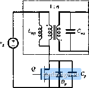 Fig. 20.44 High-voltage dc-de converter containing a resonant switch network. Problem 20.2. <a) What type of resonant switch is employed? What is the parent FWM converter? (b) Which semiconduclor devices operate wilh zero-voltage switching? With zero-current switching? (t) What is the tank resonant frequency? (d) Sketch the waveforms ot the transistor drain-to-source vohage and transformer magnetizing Current. 20J In the transformer-isolated dc-dc converter of Fig, 20.45, capacitors Cj and and inductors t[ and L/j are relatively laie in value, so that ihey have small switching ripples. The transformer model indudes an ideal l:n transformer, in conjunction with magnetizing inductance (referred to the primary side) and leakage inductances L, and tj as shown, Transistor exhibits ouiput capacitances C while the output eapacilance (jf diode is C, MOSFET Q] ct>ntains a boJy Jitide {not e\plieitly shown). Other nonidealities can be ignored. The resonant switch is well-designed, such that all eleinents listed above eimtribule lo ideal operation ofthe eonverter and resonant switch. (a) What type of resonani switch is employed? What is the parent PWM converter? (b) Which semiconductor devices operate wilh zero-voltage switching? With zero-currenl switching? 204 Л buck-boost converter is realized using a half-w-avt ZCS quasi-resonant switch. The load resistanta tias value Л, the input voltage has value V, and the converter switching frequency is f.. (a) Sketch the circuit schematic. (b) Write the complete system of equations that can be solved to determine the outpul voltage V, in terms ofthe quantities hsted above and the component values. It is not necessar> lo actually solve yuur equations. You may also quote results listed in this textbook. |