
|
| |
|
Строительный блокнот Introduction to electronics 120 Vrms 30 Hi 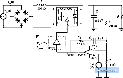 value - {LlMrr(0.5 v, 0.1,0.9)) Fig, B,19 DCM boosl rectifier example. B.2.j Example: DCM BoulsI Rectilier Converters switching at frequencies much above the ac iine frequency can be used to construct near-ideai rectifiers where power is taken from the ac iine without generation of iine current hiumonics. Approaches to construction of iow-harnionic rectifiers are discussed in Chapter IS. One simple solution is based on the boost converter operating in discontinuous conduction mode, as descritied in Section 18.2.1. When a bo[)st DCM convetter operates at a constant switch duty cycle, the input current approxitnately ftiiiows the input voltage. The DCM effective resistance 2L/d (t)T is an approximation [)f the emulated resistance /tj of the DCM boost rectitkr. Ac hne current hatmouics are not zero, but the rectifiercan still be designed to meet harmonic limits. In this section we consider a DCM boost rectifier example and test its petfottnance by simulation. An averaged circuit model of the boost DCM rectifier is shown in Fig. B.l 9. Full-wave rectified 120 Vrms, 50 Hz ac line voltage is applied to the input of the boost conveiter. The converter switches iue replaced by the CCM-DCMl averaged switch subcircuit. It is desired to regulate the dc output voltage at V= 300 V at output power up to = 120W across the load R. The switching frequency is /j. = 100 kHz. Let us select the inductance L so that the converter always operates in DCM. Frotn Eq. (18.24), the condition for DCM is: (B,21) where is the emulated resistance of the rectifier and V is the peak of the ac line voltage. When line 30iV- 3O0V 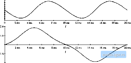 Fig, B.20 Output vnltitge and ac line ctiirenc in the DCM boost tctiher exatnple. CLittent harmonics and los.ses are neglected, die rectifier emulated resistance at the specified load power P is (B.22) Given V = 170 V and found from Eq. (B.22), Eq. (B.21) gives L < 260 цН, The selected inductance is L = 200 jlH. A low-bandwidth voltage feedback loop is closed around the converter to regulate the dc output voltage. The output voltage is sensed and compared to the reference v. A PI cotnpensator is constructed around the LM324 op-amp. The output v.y; ofthe compensator is the input to the pulse-width tnodulalor. By adjusting the switch duty ratio d, (п,; adjusts the etnuiated resistance = IL/dT of the rectifier, and thereby controls the power taken from the ac line. In steady state, the input power tnatches the output power. The dc output voltage V\s regulated at the value set by the reference voltage v and the voltage divider composed of and follows: (B.23) Modeling ofthe low-bandwidth voltage regulation loop is discussed in Section 18.4.2. It is of interest to find ac line current harmonics. First, a long transient simulation is perfortned to reach steady-state operation. Then, current hartnonics are computed using Fourier analysis applied to the ac line current waveform i (r) during one line cycle in steady state. Figure B.20 shows the steady-state ac line current and output voltage obtained for R - 900 Я, i.e., for KKlWof output power. The output voltage has a dc component equal to 300 V, and an ac ripple component at twice the line frequency. The peak-to-peak voltage ripple at twice the line frequency is approximately S V, which compares well with the value (7 V) found frotn Eq. (18.91). The ac line current has noticeable distortion. The spectrutn ofthe ac line current is shown in Fig. B.21. The largest hartnonic, the third, has an amplitude of 16.6% of the fundamental, and the total htumonic distortion is 16.7%. We can also examine what happens if the rectifier is overloaded. The steady-state ac line current wavefortn ft)r the ca.se when the load resistance is R = 51Ю fl, and the output power is 180 W, is shown in Fig. B.21 S)ectrum of the ac line cuirent in the DCM boost rectifier. SjS. 10 THD = 16.7% 3 i 7 У Harmoitic number 8 Ax THD = 71% 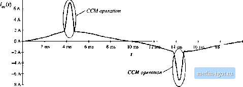 ms 20 ms Fig. B.22 Ac line cuirem of the ЕнСМ boost rectifier example, whcii the output is ovibrloudetf Fig. B.22. The boost converter operates in CCM nenr the peal; of the ac line voitage; this results in current spikes and significant harmonic distortion. CURRENT pro(;rammed control In the current programmed mode (CPM), which is studied in Chapter 12, the transistor switching is controlled so that the peak transistor current follows a control signal. The transistor duty cycle d(t) is not directly contrtilled, but depends on the CPM control input as well as on other ctmverter voltages and currents. Ill this section, large-signal averaged relationships in CPM are written in a form suitable for implementation as asuhcircuit forsimulation, b3.1 Current Programmed Mode Model for Simulation Typical inductor current and voltage waveforms of CPM converters operating in continuous conduction mtxle or in discontinuous conduction mode iue shtiwn in Fig. B.23. Signal i,(f) is the CPM control input. All artificial ramp having slope - ( is added tt) the control input. In the first subinterval, |