 | |
|
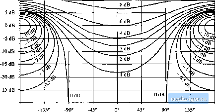
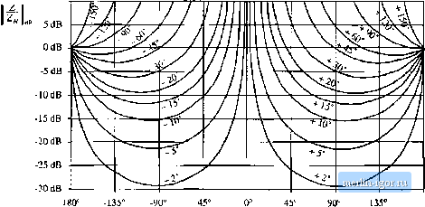
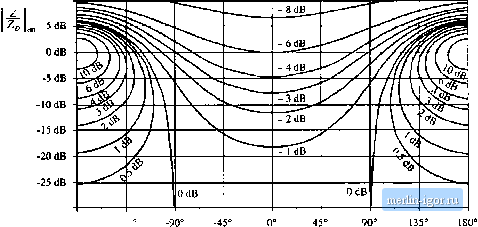
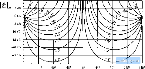
Строительный блокнот Introduction to electronics 2С/ш) ZoO-m) This equation shows how to limit the magnitude l Z(/ti)) Ц, to avoid signifieantiy changing the tiimsfer function G(s}. For quantitative design, Eqs. (C.27) and (C.2S) raise an additional question: By what factor should II Z(;tn) exceed (or be less than) \\ and ZJj(i>} , in order for the inequalities of Eq. (C.27) or (C.28) to he well satisfied? This question can be answered by plotting the magnitudes and phases of the correclion factor terms, as a function of the magnitudes and phases of {ZIZ) and(Z/Z). Figure C.6 sht)ws contours of constant 1 + Z/Z, {, as a function of the magnitude and phase of Z/Z . Figure C.7 shows similar contours of ct)nstant Z(l + Z/Z), It can be seen that, when ZtZf \\ is less lhan - 20 dB, then the maximum deviation caused by the numerator (I + ZfZ) term is less than ±1 dB in magnitude, and less than ± 7 in phase. For II Z/Z, less than - lOdB, the maximum deviation caused by the numerator (1 + 2VZ,) term is less than ± 3.5 dB in magnitude, and less than ± 20° in phase. Figures C.8 and C.9 contain contours of constant II 1/(1 + ZIZ\\ QndZl/(l + 272д), respectively, as a function of the magnitude and phase of Z/Z,j. These pk)ts contain minus signs because the terras appear in the denominator of the correction factor; otherwise, they are identical to Figs. Cb and C.7. Again, for ZyZy less than - 20 dB, the maximum deviation caused by the denominator (1 -I- Z/Zp) teem is less than ± 1 dB in magnitude, and less than ± T in phase. For [ ZiZ \\ less than ~ 10 dB, the maximum deviation caused by the denominator (1 -t- Z7Z) term is less than ± 3.5 dB in magnitude, and less than ± 20° in phase. CA EXAMPLES C.4.1 A Simple Transfer FunctioQ The first example illustrates how the Extra Element Theorem can be used to find a transfer function essentially by inspection. We are given the circuit illustrated in Fig. C.IO. It is desired to solve for the transfer function 0W = (C.2.) and to express this transfer function in factored pole-zero form. One way to do this is to employ the Extra Element Theorem, treating the capacitor С as an extra element. As illustrated in Fig. C. 11, the electrical port is taken to be at the location of the capacitor, and the original conditions are taken to be the case when the capacitor impedance is infinite, i.e., an open circuit. Under these original conditions, the transfer function is given by the voltage divider composed of resistors Д, and R, Hence, C(.9) can be expressed as Rf + R+R lOdB  -30 dB -180 180° Fig. С.Й Contours of constant I -I- 7./Z i, as a function of the magnitude isnd phase of Z/Z. 10 dB  Kig. C.7 Contours of constant ДI 4- ZlZf)), as a function of the magnilude and phase of Z/Z 10 dB  -30 (IB -180° -135 Fig. C.8 Contours of consttint j 1/(1 + Z/Z) , as a function of the magnitude und phiise of ZZp 10 dB  -30 dB -180 -135 Fig. C.9 Contours of constatitZ 1/(1 + Z/Z ), its a function of the magnitude and phaiie of Z/Z,j, |