
|
| |
|
Строительный блокнот Introduction to electronics J.2 Several Applkoitons of Power ElectroiUei 7 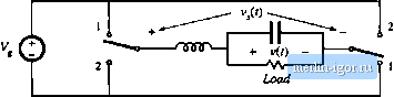 Fig. 1.13 A bridge-type dc- l0iu: inverter: (a) ideal inverter circuit, (b) typical pulse-width-modulated switch voltage waveform v/f). and its low-frequency component. 1.12 illustrates a circuit known as the boost converter, in which the positions of the inductor and SFDT switch are interchanged. This convener is capable of producing output voliages that are greater in magnitude than the input voltage. In general, any given input voltage can be converted into any desired output voltage, using a converter containing switching devices embedded within a network of reactive elements. Figure 1.13(a) illustrates a simple dc-lpac inverter circuit. As illustrated in Fig. 1.13(b), the switch duty cycle is modulated sinusoidally. This causes the switch output voltage v,(f) to contain a low-frequency sinusoidal component. The L-C filter cutoff frequency /ц is selected to pass the desired low-frequency components of v,W. but to attenuate the high-frequency switching harmonics. The controller modulates the duty cycle such that the desired output frequency and vohage magnitude are obtained. SEVERAL APPLICATIONS OF POWER ELECTRONICS The power levels encountered in high-efficiency switching converters range from (1) less than one watt, in dc-dc converters within battery-operated portable equipment, to (2) tens, hundreds, or thousands of watts in power supplies for computers and office equipment, to (3) kilowatts to Megawatts, in variable-speed motor drives, to (4) roughly 1СКЮ Megawatts in the rectifiers and inverters that interface dc transmission lines to the ac utility power system. The converter systems of several applications are illustrated in this section. A power supply system fora laptop computer is illustrated in Fig. 1.14. A lithium battery pow-er.s the system, and several dc-dc converters change the battery voltage into the voltages required by the loads. A buck converter produces the low-voltage dc required by the microprocessor. A boost converter increases the battery vohage to the level needed by the disk drive. An inverter produces high-voltage high-frequency ac to drive lamps that light the display. A charger with transformer isolation converts the ac line voltage into dc to charge the battery. The converter switching frequencies are typically in the vicinity of several hundred kilohertz; this leads to substantial reductions in the size and weight of the reactive elements. Power immagement is used, to control sleep modes in which power consumption is reduced and battery life is extended. In a distributed power system, an intermediate dc voltage appears at the computer backplane. Each printed circuit card contains high-density dc-dc converters that produce Шгийшюп ас line input 85-265 Vims Charger PWM Rectifier inverter Display hacklighiing Buck converter Microprocessor Power management Lithium battery Boost converter Disk drive Fig. 1.14 A laptop computer power supply system. locatly-regulated low voltages. Commercial applicatiotis of power electronics include off-line power systems for computers, office and laboratory equiptnent, uninterruptable ac power supplies, and electronic ballasts for gas discharge lighting. Figure 1.15 illustrates a power systetn of an earth-orbiting spacecraft. A solar array produces the tnain power bus voltage V, . DC-DC converters convert V to the regulated voltages required by the spacecraft payloads. Battery charge/discharge controllers interface the main power bus to batteries; these controllers may also contain dc-4lc converters. Aerospace applications of power electronics include the power systetns of aircraft, spacecraft, and other aerospace vehicles. Figure 1.16 illustrates an electric vehicle power and drive sy.stem. Batteries are charged by a converter that draws high power-factor sinusoidal current from a single-phase or three-phase ac line. The batteries supply power to variable-speed ac motors to propel the vehicle. The speeds of the ac motors are controlled by variation of the electrical input frequency. Inverters produce three-phase ac output voltages of variable frequency and variable magnitude, to control the speed of the ac motors and the vehicle. A dc-dc converter steps down the battery voltage to the lower dc levels required by the electronics of the systetn. Applications of motor drives include speed control of industrial processes, such as control of compressors, fans, and pumps; transportation applications such as electric vehicles, subways, and locomotives; and motion control applications in areas such as computer peripherals and industrial robots. Power electronics also finds application in other divense industries, including dc power supplies, Ditxipmin shunt regulator
Battery ckarge/diicljarge controllers Batteries  И 4- Dc-dc Rg, I.IS Power system of an earth-orbiting spacecraft. Dc-dc convener Poyload Payload bmiery 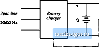 \iiriabU-firiiurncy Viriabk-volntgeii
/, i Elements of Power Electrpnicx acmachittf Inverter conlmlbia DC DC convener lyslem cortifolier
dcbta etectronics Fig, 1.16 Лп electric vehicle power and drive system, uninterruptable power supplies, and battery chargers for the lelecotntnunications industry; inverter systems for renewable energy generation applications such as wind and photovoltaic power: and utility power systems applications including liigh-voltagedc transmission and static VAR (reactive volt-ampere) compensators. ELEMENTS OF POWER ELECTRONICS One of the things that makes the power electronics field interesting is its incorporation of concepts from a diverse set of fields, including: analog circuits electronic devices control systems power systems magnetics electric machines numerical .simuiadon Thus, the practice of power electronics requires a broad electrical engineering background. In addition, there are fundamental concepts that are unique to the power electronics field, and that require specialized study, Tlic presence of high-frequency switching makes the understanding of switched-mode converters not straightforward. Hence, converter modeling is central to the study of power electronics. As introduced in Eq. (1.3), the dc component of a periodic waveform is equal to its average value. This ideal can |
||||||||||||||||||||||||||||||||||||||||||||||