 | |
|
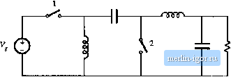
Строительный блокнот Introduction to electronics )sts Софгете. 19S5 RetorU, pp. 355-361, June 19S5. [9] N. Mohan, T. UNDELAXD, and W. ROEEINS, Power Electronics: Converters, Applicaiions. and Design, 2nii edi[., New York: John Wiley & Sons, 1995, Chaplers 19-26. [10] C. L. Мл and P. 0. LaLTRITZEN, A Simple Power Diode Model with Forward and Reverse Recovery, IEEE Power Electronics Spedalists Conference, 1991 Record, pp. 411-415, June 1991. [11] M. SCHLECHT and L. CaSEV, A Comparison of the Square Wave and Quasi-Re.sdnanl Topologies, IEEE Applied Power Eleclromcs Cotjference, 1987 Record, pp. 124-134, March I9S7. [12] В J. Baliga, Modern Power Devices, New York: John Wiley & Sons, 19S7. [13] P. Gray, D. DeWiTT. A. BootHROYD, and J. GtBEONS, Physical Electronics and Circuit Models nfTran-siswrs. Semiconductor Electronics Education Committee. Vol. 2, New York; John Wiley & Sons, 1964. [14] E. OXNER, Power FETs and Their Applications, EnglewtKKl, New Jersey: Prcnlice-Hall, 19S2. [15] M. RASHID, Power Electronics: Circuits, Devices, and Ajjplicationx, 2nd edit.. Englewood. New Jersey: Prentice Hall, 1993, Chapters 3, 4, and 8. [16] B. J. Balkia, M. S. Adler, R. P. Love, P. V. Gray, and N. D. Zammer, The Insulated Gate Transistor -A New Three Terminal MOS-Conlrolled Bipolar Power Device, IEEE Transactions on Electron Devices, Vol. 31, No. 6, pp. 821-828, June 19S4. [17] V. TeiwplE, MOS-Conirolled Thyristors-A New Class of Power Devices, IEEE Transactions on Electron Device.4, Vol. 33, No. 10, pp. 1609-161S, October 19S6. [18] S. SUL, F. ProFLTMO, G. CHO. and Т. Lll-O, MCTs and IGBTs: A Comparison of Performance in Power Elecuonics Circuits. IEEE Power Electro>iics Specialists Conference. 1989 Record, pp. 163-169, June 19S9 [19] V. Temple, S. Arthltr, D. Watrolts, R. De Doncker, and H. Metha, Megawau MOS ConiroJled Thyristor for High VtJiage Power Circuits, IEEE Power Electronics Specialists Conference, 1992 Rect)rd, pp. 1018-1025, June 1992. Problems In Problems 4.1 to 4.6, the input voltage isde and positive with the polarity shown. Specify how to implement the switches using a minimal number of ditides and transistors, such that ihe converter operates Over the entire range of duty cycles 0<ZJ< l.The switch sliites should vary as shown in Fig. 4.56. You may assume that the inductor current ripples and capacitor voltage ripples are small. For each problem, do the following: Switch position (a) Realize the switches using SPST ideal switches, and e.\plici ily define the voltage and current of euch switch. (b) Express the on-state current and off-stale voltage of each SPST switch in terms of the converter inductor currents, capacitor voltages, and/or 0 DT, T, t Fig. 4.56 Switch control method for Problems 4.1 to 4.6, input source voltage. (c) Solve the converter to dctcfminc the inductor currents and capacitor voltages, as in Chapter 2. (d) Determine the poltirides of the swiich on-slale eurrertls tind off-stute volliige.s. Do the poltirities viiry wilh duty cycle? (e) State how each switch can be realized using irunsislors und/or diodes, und wheiher the realiza-liun requires single-quadrant, current-bidirectional two-quadranl, voltage-bidirectional Iwe-quadrant, or four-quadranl switches. 1 / 2   onnn Fwbkms 19 1 9 1  © тпггг  An IGBT and silicon diode operate in a buck converter, witii tiie IGBT waveformii illustrateJ in Fig. 4.57. Tlie ctinverter tiperates wtlh Input voltage V, = 400 V, output voltage V = 200 V, and loaJ current 1 = lOA. 4O0V 40A JtBV 30 A 100 V lOA OV OA
0 1 г Fig. 4.57 [GBT voltage and current waveforms. Problem 4.7. (a) Estimute die total energy lost during die switching transitions. (b> The forward vuitage drop of [he IGBT is 1.5 V, iind the diude hiis forward voltage drop 1.5 V. All other sources of conduction loss and fixed loss can be neglected. Estimate the semiconJtictor conducuiin loss. (c) Sketch the converter efficiency over the range of switching frequencies 1 kHz <f < 100 kHz, and label numerical values. Two MOSFETs are employed as currenl-bidirecttunal iwo-tjuadranl switches in a bidirectional battery chiirger/discharger based on the dc-dc buck converter. This converter interfaces a 16 V battery to a 28 V main puwer bus. The maximum ballerv current is 40 A. The MOSFETs have on-resisliinces of 35 гаЙ. |
||||||||||||||