
|
| |
|
Строительный блокнот Introduction to electronics Their biidy diodes liiive Tonvjid voilage drops of 1.0 V, and exhibit reeuvered charge Q4( 25 and reverse recovery times of 200 ns in the given circuit. You may asstime that aii diodes in this problem have snappy reverse recovery characteristics, and also assume that diode stored ciiargc is the dominant cause of switching loss in this circuit. You may neglect all losses otltcr than the semiconductor conduction losses and the .switching loss induced by diode stored charge. The currcnt-bidircctionai two-quadrant switches are rcaiized as in Fig, 4. i()(a), utilizing the MOSFET body diodes. (a) Estimate the switching energy loss, conduction loss, and converter efticicncy, when the battery is being charged at the maximum rate. The switching frequency is iOO IcHz Extcrnai diodes arc now added as iljusttatcd tn Fig. 4.l(Xb). These diodes have forward voltage drops of 1.0 V, and exhibit recovered charge of 5 ftC and reverse recovei times of 4(1 ns in the given circuit. (b) Repeat the analysis of Part (a), for this case. (c) Over What range of switching frequencies does the addition of the cxtcraal diodes improve the convener efficiency? 49 A switching converter operates with a switching frequency of 100 kHz. The converter waveforms exhibit damped sinusoidal ringing, initiated by the transistor turn-off transition, which decays slowly but eventually reaches zero before the end of the switching period. This ringing occurs in a scries resonant circuit formed by parasitic inductances and capacitances in the circtiit. The frequency of the ringing is 5 MHz. During the first period of sinusoidal ringing, the ac inductor current reaches a peak magnitude of (1.5 A, and the ac capacitor voltage reaches a peak magnitude of 200 V, Determine the following quantities: (a) the value of the total parasitic inductance, (b) the value of the total parasitic capacitance, (c) the energy lost per switching period, associated with this ringing, and (d) the switching loss associated with this ringing. (e) Derive a general expression for the switching loss, as a function of the switching frequency, ringing frequency, and the ringing voltage and current peak magnitudes during the first period of ringing. The Discontinuous Conduction Mode When the ideal switches of a dc-dc converter arc implemented using cttrrent-nnidirectional and/or voltage-unidirectional semiconductor switclies, one or more new modes of operation known as disconthui-ous conduction modes (DCM) can occur. The discontinuous conduction mode arises when the switching ripple in an inductor current or capacitor voltage is large enough to cause the polarity of the applied switch current or voltage to reverse, such that the current- or voltage-unidirectional assumptions made m realizing the switch with semiconductor devices are violated. The DCM is commonly observed in dc-dc converters and rectifiers, and can also sometimes occur in inverters or in other converters containing two-quadrant switches, The discontinuous conduction mode typically occurs with huge inductor current ripple in a converter operating at light load and containing current-unidirectional switches. Since it is usually required that converteni operate with their loads removed, DCM is frequently encountered. Indeed, some converters arc purposely designed to opemte in DCM for all loads. The properties of converteni change radically in the discontinuous conduction mode. The conversion ratio m becomes load-dependent, and the output impedance is increased. Control of the output may be lost when the load is removed. We will see in a later chapter that the converter dynamics are also significantly altered. In this chapter, the origins of the discontinuous conduction mode are explained, and the mode boundary is derived. Techniques for solution of the converter wavefonns and output voltage are also described. The principles of inductor volt-second balance and capacitor charge balance must always be true in steady state, regardless of the operating mt)de. However, apphcation of the small ripple approximation requires some care, since the inductor current ripple (or one of the inductor current or capacitor voltage ripples) is not small. Buck and boost converters are solved as examples. Characteristics of the basic buck, boost, and buck-boost converters arc summarized in tabular form. The Disc/mumious Conduai/m Mode S.l 0RK;IN of the DISCONTINLIOLIS conduction MODE, AND MODE BOUNDARY Let us ronsider how the inductor and switch current waveforms change as the load power is reduced. Lets use the buck converter (Fig. 5.1) as a simple example. Ihe inductor current l{t) and diode current ;(f) waveforms are sketched in Fig. 5.2 for the continuous conduction mode. As described in Chapter 2, the inductor current waveform contains a dc component 7, plus switching ripple of peak amplitude Д[ . During the .second subintcrvui, the diode current is identical to the inductor current. The minimum diode current during the second subinterval is equal to (1 - since the diode is a single-quadrant switch, operation in the continuous conduction mode requires that this current remain positive. As shown in Chapter 2, the inductor current dc component 1 is equal to the load current: (5.1) since no dc current flows through capacitor C. It can be seen that I depends on the load resistance R. The Fig, 5.1 example. Buck converter 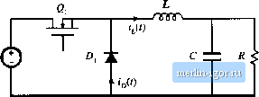 Iig, 5,2 Buck converter wave-fortes in the continuous conduction mode: (a) inductcir current if (f). (b) diode ctin-ent г(;:). Coitducmg devices: |