
|
| |
|
Строительный блокнот Introduction to electronics 5.1 Origin of ihe Dincominnous Condimiati Mode, and Mode boundary Fig, 5.3 Buck converter waveforms at tiie boandary between the contiiiunus and discdntiniious cnnduclion modes: (a) inductor current (b) diode cuiTent i (0. Conducdng devices: 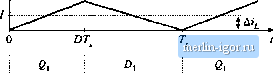 switching ripple peak amplitude is: (5.2) The ripple magnitude depends on the applied voltage (V - V), on the inductance L and on the transistor conduction time DT, But it does not depend on the load resistance R. The inductor current ripple magnitude varies with the applied voltages rather than the applied currents. Suppose now that the load resistance R is increased, so that the dc load current is decreased. The dc component of inductor current / will then decrease, but the ripple magnitude Дг will remain unchanged. If we continue to increase Д, eventually the point is reached where l-Ai, illustrated in Fig. 5.3. It can be seen that the inductor current iiit) and the diode current tp(0 are both zero at the end of the switching period. Yet the load current is positive and nonzero. What happens if we continue to increase the load resi.stance Л? Tlie diode current cannot be negative; therefore, the diode must become reverse-biased before the end of the switching period. As illustrated in Fig. 5.4, there are now three subintervals during each switching period T. During the first subinterval of lengdi />Г the transistor conducts, and the diode conducts during the second .subinterval of length DjT . At the end of the second subinterval the diode current teaches zero, and for the remainder of the switching period neither the transistor nor the diode conduct. The converter operates in the discontinuous conduction mode. Figure 5.3 suggests a way to find the boundary between the continuous and discontinuous conduction modes. It can be seen that, for this buck converter example, the diode current is positive over the entire Interval ОТ,. < I < T. provided that / > Hence, the conditions for operation in the continuous and discontinuous conduction modes are: Fig. 5.4 Buck converter wuveformi in the discotitiiluiiub; conduction mode: {л) indjctor current (f), (b) diude current Conducting devices: (b) (dC() />di7 tbrCCM l<Ai Гог1Х:М (5.3) vifhere / and are found assuming that the converter operates in the continuous conduction irnxle. Insertion of Eqs. (5.1) and (5.2) into Eq. (5.3) yields the follovifing condition for operation in the discontinuous conduction mode: (5.4) Simplification leads to 2L RT, (5.5) This can also be expressed К < K,.,ID) for DCM (5.6) where 5, / Origin of the Discontiniioiis Condnaion Made, and Made Bamidaiy Fig, 5,5 Rutk toiivcrter K,,(D) vs. o. Tlie converter operates in CCM when К > K,,. and in DCM when К < K,. , 1 D The dimensionless parameter A is a measure of the tendency of a converter to operate in the discontinuous conduction mode. Large values of К lead to continuous mode operation, while small values lead to the discontinuous nitxle for some values of duty cycle. The critical value of Aat the boundary between modes, /i.,.;,(D), is a function of duty cycle, and is equal to iJfor the buck converter. The critical value К.,,ф) is plotted vs. duty cycle D in Fig. 5.5. An arbitrary choice of A is also illustrated. For the values shown, it can be seen that the converter operates in DCM at low duty cycle, and in CCM at high duty cycle. Figure 5.6 illustrates what happens with heavier loading. The load resistance .fi is reduced in value, such that ffis larger If A is greater than one, then the converter operates in the continuous conduction mode for all duty cycles. It is natural to express the mode boundary in terms of the load resistance fi, rather than the diraensionless parameter A. Equation (5.6) can be rearranged to directly expose the dependence of the mode boundary on the load resistance: R < R,rtp) for CCM R > Rcr;,(P} for DCM (5.7) where So the converter enters the discontinuous conduction mode when the load resistance R exceeds the critical value /f.jj. This critical value depends on the inductance, the switching period, and the duty cycle. Note that, since [У < 1, the minimum value of fiif i.T.. Therefore, if Я < Ihen the converter will operate in the continuous conduction mode for all duty cycles. These results can be applied to loads that are not pure linear resistors. An effective load resis- Fig. 5,6 Comparison of К with /, ,(/J), for a larger value of A , Since/C> 1. the converter operates in CCM for all D. 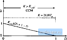 |