
|
| |
|
Строительный блокнот Introduction to electronics 52 Amhsis of the Omversimi Ratio M(D, K) Fig. 5,8 Inductor voltage waveform ij(f), buck ciinverter operating in discottnmious conduction mode, another eqtiation is needed toeliminate and solve for the output voltage V. The second equation is obtained by use of capacitor charge balance. The connection of the capacitor to it.s adjacent components is detailed in Fig. 5,9. The node equation of thi.s network is By capacitor charge balance, the dc component of capacitor current must be zero: (5.20) (5.21) Therefore, the dc load current must be .supplied entirely by the other element.s connected to the node. In particular, for the case of the buck converter, the dc component of inductor current must be equal to the dc load current: (5.22) So we need to compute the dc component of the inductor current. Since the inductor current ripple is not small, determination of the inductor current dc component require.s that we examine the current waveform in detail. The inductor current waveform is .sketched in Fig, 5.10. The current begins the .switching period at zero, and increases during the first subinterval with a constant slope, given by the applied voltage divided by the inductance. The peak inductor current ij, IS equal to the constant slope, multiplied by the length of the first subinterval: V,-V i,(0,r,) = v = -D,r, (5.23) The dc component of the inductor current is again the average value: (5.24) Ftg, 5.9 Conncctiov! of ihe oiitpnt capaciuir to adjacent components. 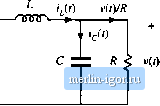 Fig. 5.10 Iruluctorturrent waveform 1,0), buck convuiter iipciatuig in clis-tonliiiuous conduction mode. 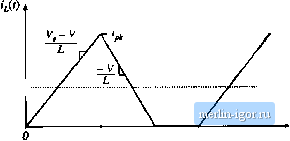 The integral, or area under tlie iL(t) ctuve, is the area of the triangle having lieiglit ij and base dimension (D[ + 02)Г,. Use of tlie triangle area formula yields Substitution of Eqs. (5.23) and (5.25) into Eq. (5.24) ieads to Finally, by equating this result to the dc load current, according to Eq. (5.22), we obtain (5,25) (5.26) (5.27) Thus, we have two unknowns, V and D e have two equations. The first equation, Eq. (5.19), was obtained by inductor volt-second balance, while the second equation, Eq. (5,27), was obtamed using capacitor charge balance. Elimination of D from the two equations, and solution for the voltage conversion ratio M(D K)=V/V, yields t+./1+ where vulid for (5.2S) KIURT, This is the solution of the buck converter operating in discontinuous conduction mode. The complete buck converter characteristics, including both continuous and discontinuous conduction modes, are therefore 5.3 Boos! Convener Example Fig. 5.11 Voltage conversion ratio M(D, fT), buck converter. 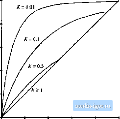 1+./1+ (5.29) where the transistor tiiity cycle D is identical to the subinterval 1 duty cycle D, of the above derivation. These characteristics are plotted in Fig. 5.11, for several values of A. It can be seen that the effect olthe discontinuous conduction mode is to cause the output voltage to increase. As К tends to zero (the unloaded case), M tends to unity for all nonzero D. The characteri.stics are continuous, and Eq. (5.28) intersects the CCM characteristic M -Dm the mode boundary. BOOST CONVERTER EXAMPLE As a second example, consider the boost converter of Fig, 5.12, Lets determine the boundary between modes, and solve for the conversion ratio in the discontinuous conduction mode. Behavior of the boost converter operating in the continuous conduction mode was analyzed previously, in Section 2,3, and expressions for the inductor current dc component / and ripple peak magnitude Ai, were found. When the diode conducts, its current is identical to the inductor current As can be seen from Fig. 2.18, the minimum value of the inductor current durmg tlie diode conduction subinterval DT<l<l\Jx (/- Д/,), If this minimum current is positive, then the diode is forward-biased for the entire subinterval < t < 7 , and the converter operates in the continuous conduction mode. So the conditions lor operation of the boost converter in the continuous and discontinuous conduction modes are: |