 | |
|
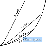
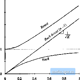
Строительный блокнот Introduction to electronics Fig, 5.19 ullage tonveisioii ratio M(D, K) of tlie boQst cuiiveiter, including both continuous and di.scontinaous conduction niudcs  0,25 0,75 These characteristics are plotted in Fig. 5.19, for several values of k. As in the buck converter, the effect of the discontinuous conduction mode is to cau.se the output voltage to increase. The DCM portions of the characteristics are nearly linear, and can be approximated as (5.54) SUMMARY OV RESULTS AND KEY POINTS The characteristics of the basic buck, boost, and buck-boost arc summarized in Table 5.2. Expressions for KyfD), as well as for the solutions of the dc conversion ratios in CCM and DCM, and for the DCM diode conduction duty cycle D are given. The dc conversion ratios of the DCM buck, boost, and buck-boost converters are compared in Table 5.2 .Summary of CCM-13CM cliaracterisiies for die liuck, boost, and txjck-boost converters Converter DCM M(D, K) DCM Dj(0, CCM M{D) Buck Boost Buck-boost (1-fl) D{1 - of (l-O) 1+1 + 4А-/0= l/l4Д/f 2 D ~ Ш §м(д/о 1 -D D 1-D with DCM occur.s for k<k ,. 5.4 Siimmary ofRe.wla and Key Points Fig. 5.20 Comparison of de conversion raiio.s of the buck-hoost, buck, atid boost converters operated in the discontinuous conduction mode.  Fig. 5.20, The buck-boost characteristic is a line with slope The characteristics of the buck and the boost converters are both asymptotic to this line, as well as to the line M= I. Hence, when (iperaled deeply into the discontinuous conduction mode, the boost converter characteristic becomes nearly linear with slope I/, especially at high duty cycle. Likewise, the buck converter ohtiracteristic becomes nearly linear with the same skjpe, when operated deeply into discontinuous conduction mt)de at low duty cycle. The following are the key points of this chapter: 1. The discontinuous conduction mode occurs in converters containing current- or voltage-unidirectional switches, when the mductor current or capacitor voltage ripple in large enough to cause the switch current or voltage to reverse polarity. 2. Ctmditions for operation in the discontinuous conduction mode can be found by determining when the inductor current or capacitor voltage ripples and dc components cause the switch on state current or off stale voltage to reverse polarity. 3. The dc conversion ratio jV/ of converters iiperating in the discontinuous conduction mode can be found by application of the principles uf inductor voh-second and capacitor charge balance. 4. E.stra care is required when applying the small-ripple approximation. Some waveforms, such as the output voltage, should have small ripple which can be neglected. Other wavefin-ms. such as one or more inductor currents, may have large ripple thai cannot be ignored. 5. The characteristics of a converter changes significantly when the converter enters DCM. The output voltage becomes load-dependent, resulting in an increase in the converteroutput impedance. 116 The Discmnnuom Coiiduaioii Mode Problems * The elemenLs of Lhe buck-boosi converter of Fig. 5.21 are ideak all losses may be ignored. Your resuits for parLs (a) and (h) shoaid agree with Tabie 5.2.  Fiju, S.21 lluck-biKist ctsnverter (if Piohletiis 5.1 and 5.13. (a) Show that tlie converter operates in discontinuous conduction mode when К < ff and derive expressions for К and A. . (b) Derive an expression for the dc conversion ratio VIV oi the buck-boost converter operating in discondnuous conduction mode. (c) For K=O.L plot V/V over the etitire ratige (}<.D<.[. (d) Sketch the inductor voltage and currenl wavefornis for A = 0.1 and D = 0.3. Label salient features. (e) What happens to Vat no load (H Explain why. physically. 5.2 A certain buck converter contains a synchronous rectifier, as described in Section 4.1.5. (a) Does this converter operate in the discontinuous conduction mode al light load? Explain. (b) The load resistance is disconnected (K -> °°], and the converter is operated with duty cycle 0.5. Sketch the inductor current waveform. 5J An unregulated dc input voltage varies over the range 35 V < V, < 70 V. A buck converter reduces this voltage to 28 V; a feedback loop varies the duty cycle as necessary such that the convener otitptit voltage is always equal to 28 V. The load power varies over the range 10 W<r, £ lOOO W. The element values arc: Z, = 22fdf C = 470fiF /, = 75 kHz Losses may be ignored. (a) Over what range of and load current does the converter operate in CCM? (h) Determine lhe maximum and minimum values of the steady-state transistor duly cycle. SA The transistors in the converter of Fig. 5.22 are driven by the same gate drive signal, .so thai they turn on and off in synchronism with duty cycle D. (a) Determine the conditions under which this converter operates in the discontinuous conduction mode, as a ftinciion of the steady-state duty ratio D  Fig, 5,22 Walkiiis-Jtiliiistm converter of Problem 5.4. |