 | |
|
Строительный блокнот Introduction to electronics dc source ± ТППГ фас food  + v.. - source Jc source 3cload 
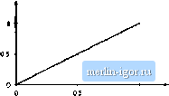
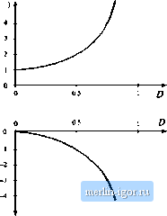
Fig. 6.13 Ос-Зфас i[ivi;in;i topologies: (a) dHlerentiai conneclioii оГЗф ioad atioss nutpiits of bncl; torvcrteri: (b) siinplitlcatiou of low-pass (ilters to obtain the ilc-Зфао vciltage-source inverter; (c) the (с-3()ае carrent-sourcc i iivcrtcr. If the converter oiitpiit voltages V V, and Vy contain the same dc bias, then this dc bias will also appear at the netitral point V , The phase voltages V , V , and V , are given by It can be seen that the dc biases cancel ont, and do itot appear in V, V and V. . Let us reabze converters 1, 2, and 3 of Fig. 6.12 using buck converters. Figure 6.13(a) is theit obtained. The circuit is re-drawn in Fig. 6.13(b) for clarity. This converter is known by several names, including the voltage-source inverter and the buck-derived three-phase bridge. Inverter circuits based on dc-dc converters other than the buck converter can be derived in a similar manner. Figure 6.13(c) contains a three-phase ctitrent-fed bridge converter having a boost-type voltage conversion ratio, also known as the current-source inverter. Since most inverter applications require the capability to reduce the voltage magnitude, a dc-dc buck converter is usually cascaded at the dc input port of this inverter. Several other examples of three-phase inverters are given in [5-7], in which the converters are capable of both increasing and decreasing the voltage magnitude. 6.2 A SHORT LIST OF CONVERTERS An infinite number of converters are possible, and hence it is not feasible to list them all. A short list is given here. Lets consider first the class of single-input single-otitptit converters, containing a single inductor. There are a limited number of ways in which the inductor can be connected between the source and load. If we assume thatthe switching period isdivided into two subintervals, then the inductor should be connected to the source and load in one inanner during the first subinterval, and in a different manner during the second stibinterval. One can examine all ofthe possible combinations, to derive the complete set of converters in this class [8-10]. By elimination of redundant and degenerate circuits, one finds that there are eight converters, listed in Fig. 6.14. How the converters are coiinted can actually be a matter of semantics and personal preference; for example, inany people in the field would not consider the noninverting buck-boost converter as distinct from the inverting buck-boost. Nonetheless, it can be said that a converter is defined by the connections tietween its reactive elements, switches, source, and load; by how the switches are realized; and by the numerical range of reactive element values. The first four converters of Fig. 6.14, the buck, boost, buck-bm)St, and the noninverting buck-boost, have tieen previously discussed. These coiiverters prtxluce a unipolar dc output voltage. With these converters, it is possible to increase, decrease, and/or iiivert a dc voltage. Converters 5 and 6 are capable of producing a bipolar output voltage. Converter 5, the H-bridge, has previously been discussed. Converter 6 is a nonisolated version of a push-pull current-fed converter [ 11-15]. This converter can also produce a bipolar otitput voltage; however, its conversion ratio M(D) is a nonlinear function of duty cycle. The number of switch eleinents can be redticed by using a two-winding inductor as shown. The function of the inductor is siinilar to that of the flyback converter, discussed in the next section. When switch 1 is closed the upper winding is used, while when switch 2 is closed, current flows through the lower winding. The current flows through only one winding at any given instant, and the total ampere-turns of the two windings are a continuotis function of time. Advantages of this converter are its grotind-referenced load and its ability to produce a bipolar output voltage using only two SPST current-bidirectional switches. The isolated version and its variants have found Convener агаш 1. Buck 2. Boost 3. Buck-boost М(П) = D M(£>) 1 1-d   1 D  4. Nonijwerting buck-boost M(D) = j I 2 e л--1  1 d Fig. 6,14 Eight members of the basic class of single-input single-output converters containing a single inilLiclor. application in high-voltage dc power supplies. Converters 7 and 8 can be derived as the inverses of converters 5 and 6. These converters are capable of interfacing an ac input to a dc output. The ac input current waveform can have arbitrary waveshape and power factor. The class of single-input single-output ctniverters containing two inductors is much larger. Several of its members are listed lit Fig. 6.15. Tlte 6uk converter has been previously discussed and ana- |
||||||||||||||||||||||||