
|
| |
|
Строительный блокнот Introduction to electronics Fig. 6.17 S- characteristics of tmnsformer core. 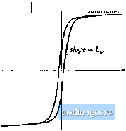 The magnetizing current i(t) is proporlioiiai to the magnetic field H(l) inside the transformer core. The physical B-H characteristics of the transformer core material, iiiiistrated in Fig. 6.17, govem the magnetizing ciiirent behavior. For example, if the magnetizing current (д/f) becomes too large, then the magnitude of the magnetic field H{t) causes tlte core to saturate. The magnetizing inductance then becomes very small in value, effectively shorting out the transformer. The presence of the magnetizing indiictance explains why transformers do not work in dc circuits: at dc, the magnetizing inductance has zero impedance, and shorts out the windings. In a well-designed transformer, the impedance of the magnetizing inductance is large in magnitude over the intended range of operating frequencies, such that the magnetizing ciiireitt has much sinaiier magnitude than ij(f). Then !;((). and the transformer behaves nearly as an ideal transformer. It should be emphasized that the magnetizing current 1(0 and the primary winding current i[(f) are independent quantities. The magnetizing inductance must obey all of the usual rules for inductors. In the model of Fig. 6.16(b), the primary winding voltage v(f) is applied across Z,y, and hence (6.17) Integration leads to v,(T)J-c (6.11!) So the magnetizing current is determined by the integral of the applied winding voltage. The principle of inductor volt-second balance also applies: when the converter operates in steady-state, the dc component of voltage applied to the magnetizing inductance must be zero: v,(t)dt (6.19) Since the magnetizing current is proportional to the integral of the applied winding voltage, it is important that the dc component of this voltage be zero. Otherwise, during each switching period theie will be a net increase in magnetizing cuirent, eventually leading to excessively large currents and transformer saturation. The operation of converters containing transfonners inay be understood by inserting the model of Fig. 6.16(b) in place of the transformer in the converter circuit. Analysis then proceeds as described in the previoiis chapters, treating the magnetizing indttctance as any other inductor of the converter Practical transformers must also contain leakage inductance. A small part of the flux linking a winding may not link the other windings. In the two-winding transformer, this phenomenon may be modeled with small inductors in series with the windings. In most isolated converters, leakage inductance is a nonideality that leads to switching loss, increased peak transistor voltage, and that degrades cross-regulation, but otherwise has no infliience on basic converter operation. There axe several ways of incorporating transformer isolation into a dc-dc converter. The full-bridge, half-bridge, forward, and piish-pull converters are commonly tised isolated versions of the bttck converter Similar isolated variants of the boost converter are known. The flyback converter is an isolated version of the buck-boost converter. These isolated converters, as well as isolated versions ofthe SEPIC and the converter, are discussed in this section. 63.1 Full-Bridge and Half-Bridge Isolated Buck Converters The full-bridge transformer-isolated buck converter is sketched in Fig. 6.18(a). A version containing a center-tapped secondary winding is shown; this circuit is cominonly used in converters producing low output voltages. The two halves of the center-tapped secondary winding may be viewed as separate windings, and hence we can treat this circuit element as a three-winding transformer having turns ratio l;n:n. When the transfonner is replaced by the equivalent circuit triodel of Fig. 6.16(b), the circtiit of Fig. (a) 71 - Tl - i AW И* Fig. 6,18 Full-bridge transformcr-fsolatcd huck ccmverter: (a) schematic diagram, (b) replacement cif transforms: with equivalent circuit model. Hg. 6.1V Waveforns of the fuU-bridgc traiiaforEiicr-isolatcd buck converter. ccndticiing devices: I L 0.5 i 0.5/ 6.18(b) is obtained. Typical waveforms are illustrated in Fig. 6.19. The output portion of tlie converter i.s similar to the nonisolated buck converter-compare the v/f) and ;(/) waveforms of Fig. 6.i9 with Figs. 2.1(b) and 2.10. During the first subinterval 0 < t < 0/j., transistors Qj and Q conduct, and the transformer primary voltage is f j. = V.. This positive voltage causes the magnetizing current iyf(t) to increase with a slope aiVJLyi. The voltage appearing across each half of the center-tapped secondary winding is/iV, with the polarity mark at positive potential. Diode is therefore forward-biased, and is reverse-biased. The voltage v/f) is then equal to flV, and the output filter inductor current i{t) flows through diode Dy Several transistor control schemes are possible for the .second subinterval DT < I < T,.. In the most common scheme, all four transistors are switched off, and hence the transformer voltage is Vj- = 0. Alternatively, transistors and could conduct, or transistors and could conduct. In any event, diodes and /Jf, are both forward-biased during this subinterval; each diode conducts approximately one-half of the output filter inductor current. Actually, the diode currents rj; and (jf, during the second subinterval are functions of both the output inductor current and the transformer magnetizing current. In the ideal case (no magnetizing current), the transformer causes 1 (0 and ii,(,U) to be equal in magnitude since, if i\r) = 0, then ni(t) - riijlt). But the sum of the two diode currents i.s equal to the output inductor current: |