
|
| |
|
Строительный блокнот Introduction to electronics (6.20) Therefore, it tnu.st be tme that /jjj = /д = 0,5/ duritig the .second subinterval. Iti practice, the ditjde cur-ceitts differ slightly from this residt, because ofthe nonzero magnetizing current. The ideal transfortner currents in Fig, 6.18(b) obey i()-n(D,(0 + Nt () = 0 The node equation at the primary of the ideal transformer is Elimination of i(/) from Eqs. (6.21) and (6.22) leads to (/)-п( 5(() + лги(0=1и() (6,21) (6.22) (6.23) Equations (6.23) and (6.20) describe, in the general case, the transformer winding currents during the second subinterval. According to Eq. (6.23), the magnetizing current ifj,i) may flow through the primary winding, through one ofthe secondary windings, or it may divide between all three of these windings. How the division occurs depends on the i-v characteristics of the conducting transistors and diodes, and on die transformer leakage inductances. In the case where /j = 0, the solution to Eqs. (6.20) and (6.23) is (6.24) Provided that (д /м, then i and i are each approxitnately 0.5i. The next switching period, < ( < 2Г, proceeds in a similar manner, except that the transformer is excited with voltage ofthe opposite polarity. During < f < (Г + DT), transistors Й2 and 63 and diode ZJg conduct. The applied transformer primary voltage is Vj= - V, which causes the magnetizing current to decrease with slope - V,/Ljj. The voltage v,.(r) is equal to nV, and the output inductor current /(;) flows through diode D, Diodes and again both conduct during (T -1- OTf) < t < with operation similar to subinterval 2 described previously. It can be seen that the switching ripple in the output filter elements has freqitency f- UT. However, the transformer waveforms have frequency By application of the principle of inditctor volt-second balance to the magnetizing inductance, the average value ofthe transformer voltage V-j(i) must be zero when the converter operates in steady state. During the first switching period, positive volt-seconds are applied to the transformer, approximately equal to Vj, - Qi and 64 forward voltage drops Qi and conduction time (6.25) During the next switching period, negative volt-seconds are applied to the transformer, given by - - and Q, forward voltage drops and conduction time (6.26) The net voh-secoiids, (hat is, the sura of Ец.ч. (6.25) and (6.26), .should equal zero. While the full bridge scheme cau.ses this tu be approximately true, in practice there exist imbalances such as small differences in the transistor forward voltage drops or in the transistor switching times, so thatvy) is small but nonzero. In conseqtience, dming every two switching periods there is a net inctease in the magnitude of the magnetizing current. This increase can cause the transistor forward voltage drops to change such that small imbalances are compensated. However, if the imbalances are too large, then the magnetizing current becomes large enough to saturate the transforiner. Transformer saturation under steady-state conditions can be avoided by placing a capacitor in series with the transformer priinary. Imbalances then induce a dc voltage coinponent across the capacitor, rather than across the transformer primary. Another solution is the use of current-programmed control, discussed in a later chapter. Tlte series capacitor is omitted when curreiit-prograinmed control is used. By application of the principle of volt-second balance to the output fdter inductor L, the dc load voltage must be equal to the dc component of v,(r); V = {v) (6.27) By inspection of the vjj) waveform in Fig. 6.19, (f,) = 4DV. Hence, V = nDV (6.2a) So as in the buck converter, the output voltage can be controlled by variation of the transistor duty cycle D. An additional increase or decrease of the voltage can be obtained via the physical transformer turns ratio n. Equation (6.28) is valid for operation in the continuous conduction mode; as in the nonisolated buck convetter, the full-bridge and half-bridge converters can operate in discotitinuous conduction tnode at light load. The converter can operate over essentially the entire range of duty cycles Q< D< 1, Transistors Q, and 6, must not conduct simultaneously; doing so would .short out the dc .source V, causing a shoot-throiigh current spike. This transistor crim-cimdt\cti<m condition can lead to low efficiency and transistor failure. Cross conduction can be prevented by introduction of delay between the turn-off of one transistor and the turn-on of the next transistor. Diodes D[ to ensure that the peak transistor voltage is limited to the dc input voltage V, and also provide a conduction path for the transformer magnetizing current at light load. Details of the switching transitions of the full-bridge circuit are discussed further in a later chapter, in conjunction with zero-voltage switching phenomena. The full-bridge configuration is typically used in switching power supplies at power levels of approximately 750 W and greater It is usually not used at lower power levels because of its high parts count-four transistors and their associated drive circuits are required. The utilization of the transformer is good, leading to small transformer size. Tn particular, the utilization of the transformer core is very good, since the transformer magnetizing current can be both positive atid negative. Hence, the entire core В-И loop can be used. However, in practice, the flux swing is usually limited by core loss. The transformer priinary winding is effectively utilized. But the center-tapped secondary winding is not, since each half of the center-tapped winding transmits power only during alternate swilching periods. Also, the secoiidaiy winding currents during subinterval 2 lead to winding power loss, but not to transmittal of energy to the li>ad. Design of the transformer of the full-bridge configuration is discussed in detail in a later chapter. The half-bridge transformer-isolated buck converter is illustrated in Fig. 6.20. Typical waveforms are illustrated in Fig. 6.21. This circuit is similar to the full-bridge of Fig. 6.16(a), except transistors Йз and Q, and their antiparallel diodes, have been replaced with large-value capacitors and C,. By volt-second balance of the transformer magnetizing inductance, the dc voltage across capacitor is equal to the dc component of the voltage across transistor Q orO.JV.The transformer primary voltage 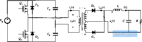 Rg. 6.2ft Half-bridge Iransftnmer-isolated buck converter. Fig, 6.21 Wavefornns of tlic half-bridge (raiisforiner-isolated buck converter 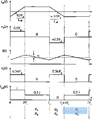 conducting i devices: \ V;(t) is then 0.5V when tian.sistur Q conduct.4, and - O.SV when transi.stor conducts. The magnitude of VjQ) is half a.s large а.ч in the full-bridge configuration, with the result that the output vidtage is reduced by a factor of 0.5: V = 0,5 DV, (6.29) |