
|
| |
|
Строительный блокнот Introduction to electronics The factor of 0.5 can be compensated for by doubling the transftwraer tuiTt.4 ratio n. However, this causes the transistor currents to double, So the half-bridge configuration needs only two transistors rather than four, but these two transistors must handle currents that are twice as large as those of the full-bridge circuit. In consequence, the half-bridge configuration finds application at lower power levels, for which transistors with sufficient current rating are readily available, and where low parts count is important. Utilization of the transformer core and windings is essentially the same as in the full-bridge, and the peak transistor voltage is clamped to the dc input voltage V, by diodes D and It is possible to omit capacitor C if desired. The current-programmed mode generally does not work with half-bridge converters. 63.2 Forward Converter The forward converter is illustrated in Fig. (i22. This transformer-isolated converter is based on the buck converter. It requires a single transistor, and hence finds application at power levels lower than those commonly encountered in the full-bridge and half-bridge configurations. Its nonpulsating output current, shared with other buck-derived converters, makes the forward converter well suited for applications involving high output currents. The maxiniuni transistor duty cycle is limited in value; for the common choice ttj = the duty cycle is limited to the range 0 < i) < 0.5. The transformer magnetizing current is reset to zero while the transistor is in the off-state. How this occurs can be understood by replacing the three-winding transformer in Fig. 6.22 with the equivaleni circuit of Fig. 6.16(b). The resulting circuit is illustrated in Fig. 6.23, and typical waveforms are given in Fig. 6.24. The magnetizing inductance L, in conjunction with diode D, must operate in the discontinuous conduction mode. The output inductori, in conjunction with diode Dj, may operate in either continuous or discontinuous conduction mode. The waveforms of Fig. 6.24 are sketched for continuous mode operation of inductor L. During each switching period, three subintervals then occur as illustrated in Fig. 6.25. During subinterval 1, transistorfli conducts and the circuit of Fig. 6.25(a) is obtained. Diode becomes forward-biased, while diodes D, and D, are reverse-biased. Voltage is applied to the transformer primary winding, and hetice the transformer magnetizing current if{() increa.ses with a slope of yjsi illustrated in Fig. 6.24. The voltage across diode fJj is equal to V, multiplied by the turns ratio The second subinterval begins when transistor Qj is switched off. The circuit of Fig. 6.25(b) is 1 : /tj : n 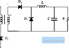 Fig. 6.22 .Single-transistor forward converter. Fig. 6.23 Forward coiwcrtcr, with transformer equivalent eircuit model. С ziz Л < V Fig. 6.24 Waveforms of the forward converter.
then obtamed. The transformer magnetizing current i/it) at this instant is positive, and must continue to flow. Since transistor is off, the equivalent circuit model predicts tliat the magnetizing current must flow into the primary ofthe ideal transformer. It can be seen that ПГу, ampere-turns flow out ofthe polarity tnark ofthe primary winding. Hence, according to Eq. (6.16), an equal number of total ampere-turns must flow into the polarity marks of the other windings. Diode prevents current from fk)wing into the 2 : 3 2iOti г D. off 1 2 : 3 fi, off J
1 : : И,
Q, off £), off I I Hg. 6.25 Forward convener circuit: (a) during subinterval 1, (b) during subinterval 2, (c) during subinterval 3. polarity mark of winding 3. Hence, the current: itii/flj polarity mark of winding 2. So diode D[ becomes forward-biased, while diode reverse-biased. Voltage V is applied to winding 2, and hence the voltage across the magnetizing inductance is - Vjtii/Hj, referred to winding I. This negative voltage causes the irtagiietizing current to decrease, with a slope of - [/ 2* Sitice diode Dj - reverse-biased, diode must turn on to conduct the output inductor cutxent г(г). When the inagnetizing current reaches zero, diode Л, becomes reverse-biased. Subinterval 3 then begins, and the circuit of Fig. 6.25(c) is obtained. Elements 2r. O and operate in the off state, and the magnetizing current remains at zero for the balance of the switching period. By application of the principle of inductor volt-second balance to the transformer magnetizing |
|||||||||||||||||||||||||||||||||||||||||||||||