
|
| |
|
Строительный блокнот Introduction to electronics Fig. 6.26 Magnetizing current waveform, forward converter: (a)DCM, f <0,5;(b)CCM,D>0,5. f*) ,-(() 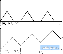 inductance, tlie primary winding voltage v(t) tniist liave zero average. Referring to Fig. ft.24, the average of ij(f) is given by (v,)-D[V) + Oj[-V / ,) + D3(0) = 0 Solution for the duty cycle yields Note that the duty cycle cannot be negative. But since D + + Dj = 1, we can write (6.30) (6.31) (6,32) Substitution of Eq. (6.31) into Eq. (6.32) leads to Solution for D then yields Д,= 1-01+ >0 So the maximum duty cycle is limited. For the common choice = fJj, the limit becotnes (6.33) (6.34) (6.35) If this limit is violated, then the transistor off-time is insufficient to reset the transformer magnetizing current to zero before the end ofthe switching period. Transfortner saturation may then occur. The transfortner magnetizing current waveform 1д(() is illustrated in Fig. 6.26, for the typical case where = itj. Figure 6.26(a) illustrates cpetation with D Й: 0.5. The magnetizing inductance, in conjunction with ditxle D, operates in the discontinuous conduction mode, and iit] is reset to zero before the end of each switching period. Figure 6.26(b) illustrates what happens when the transistor duty cycle D is greater than 0.5. There is then no third subinterval, and the magnetizing inductance operates in continuous conduction mode. Furthermore, subinterval 2 is not long enough to reset the magnetizing cut-rent to zero. Hence, there is a net increase of г(г) over each switching period. Eventually, the magnetizing current will become large enough the saturate the transfortner. The converter output voltage can be found by application of the principle of inductor volt-second balance to inductor L. Tlte voltage across itiductor L must have zero dc component, and therefore the dc output voltage Vis equal to the dc component of diode voltage Vjji(). The waveform Vjj(0 is illustrated in Fig. 6.24. It has an average value of Пу J, (6,36) This is the solution of the forward converter in the continuous conduction mode. The solution is subject to the constraint given in Eq. (6.34). It can be seen from Eq. (6.34) that the maximum duty cycle could be increased by decreasing the turns ratio щ1п. This would cause ! (() to decrease more quickly during subinterval 2, resetting the transformer faster. Unfortutiately, this also increases the voltage stress applied to transistor (3] The maximum voltage applied to transistor Q occurs during subinterval 2; solution of the circuit of Fig. 6.25(b) for this voltage yields (6.э7) For the comiuoti choice н, = Hj, the voltage applied to the transistor during subinterval 2 is 2V. In practice, a somewhat higher voltage is observed, due to ringing associated with the transformer leakage inductance. So decreasing the turns ratio allows increase of the maximum transistor duty cycle, at the expense of increased transistor blocking voltage, A two-transistor version of the forward converter is illustrated in Fig. 6.27. Transistors and are controlled by the same gate drive signal, such that they both conduct during subinterval 1, and are off during subintervals 2 and 3. The secondary side of the converter is identical to the single-transistor forward converter; diode ii- conducts during subinterval 1, while diode D conducts during subintervals 2 and 3. During subinterval 2, the magnetizing current /jy(0 forward-biases diodes and Щ, The trans- 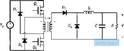 Pig. 6.27 Two-transistor forward converter. former primary winding is then oonnected to V, with polarity opposite that of subintervai I. The magnetizing current theti decreases, with siope - V/i.,. When the tnagnetizing current reaches zero, ditxles and become reverse-biased. Tlie magnetizing current then remains at zero for the baiance of the switchitig petiod. So opetatioti ofthe two-transistor forward converter is simiiar to the sitigle-transistor forward converter, in which л, = ij.The duty cycle is limited to D <0.5. This converter Ьа.ч the advantage that the tiatisistor peak blocking voltage is limited to V, and is clamped by diodes D, atid O.Typical power levels of the two-transistor forward converter are similar to those of the half-bridge configuration. The utilization of the transformer ofthe forward converter is quite good. Since the transformer magnetizing current cannot be negative, only half of the core B-H loop can be used. This would seemingly imply that the transformer cores of forward converters should be twice as large as those of full- or half-bridge converters. However, in modern high-frequency converters, the flux swing is constrained by core loss rather than by the core material saturation flux density. In consequetice, the utilization of the transformer core of the forward converter can be as good as in the full- or half-bridge configurations. Utilization ofthe primary and secondary windings of the transformer is better than in the full-bridge, half-bridge, or push-pull configurations, since the forward converter requires no center-tapped windings. During subinterval 1, all ofthe available winding copper is used to transmit power to the load. Essentially no unnecessary current flows during subintervals 2 and 3. Typically, the magnetizing current is small compared to the reflected load current, and has negligible effect on the transformer utilization. So the transformer core aud windings are effectively utilized in modern forward converters. 6,3.3 Push-PuU Isolated Buck Converter The push-pull isolated buck converter is illustrated in Fig. 6.2S. The secondary-side circuit is identical with the full- and half-bridge converters, with identical waveforms. The primary-side circuit contains a center-tapped winding. Transistor conducts fortitne ОТ, during the fust switching period. Transistor Qj conducts for an identical length of time during the next switching period, such that volt-second balance is maintained acro.ss the transformer primary winding. Converter waveforms are illustrated in Fig. 6.29. This converter can operate oven the entire range of duty cycles 0 < D < 1. Its conversion ratio is given by V=nDV. (6,38) This converter is sometimes used in conjunction with low input voltages. It tends to exhibit low primary- Fig. 6.28 Push-pull i,solated buck cotiveriei. 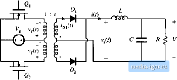 |