
|
| |
|
Строительный блокнот Introduction to electronics iit) ТЛЛГ - ouu -r 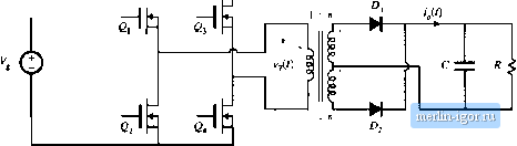 Fig. rt,34 PuH-bntlgti trunsormeir-istjIijLed boost ctinvertci. Conducting devices: 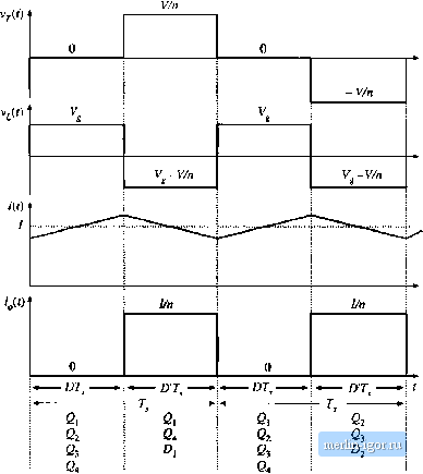 Fig* <>ь35 WiLveform.4 oflhe traiisfonnei-lsobted full-bridgt; Ьооа\ t;tiiiveiitf] , CCM. increases with slope VJL, and eiieigy is transferred from the de source V to inductor L. During the second subinterval, transistors and Q- operate in the off state, so that inductor L is connected via transistors fii and 64 through the transformer and diode to the dc output. The next switching period is similar, except that during subinterval 2, transistors 2; and operate in the off .state, and inductor L is connected via transistors and through the transformer and diode to the dc output. If the transistor off-times and the diode forward drops are identical, then the average transformer voltage is zero, and the net volt-seconds applied to the transformer magnetizing inductance over two switching peritjds is zero. Application ofthe principle of inductor volt-second balance to the inductor voltage waveform vit) yields (6.48) Solution for the conversion ratio M(D) then leads to (6,4)) This result is similar to the btKJSt converter M[D\ with an added factor of u due to the transformer turns ratio. The transistors must block the reflected load voltage V/ii - VJD. In practice, additional voltage ( ) 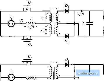 R < V Щ 1 CZtZ R < V Tl Г Fig. 636 Pusli-pull isolated converters; (a) based on the bousr converter, (b) based on the Watkins-Johnson convener. is observed due to ringing associated with the transformer leakage inductance. Because the instatitaneous transistor curretit is limited by inductor L, saturation of the transformer due to small imbalances in the semiconductor forward voltage drops or conduction times is not catastrophic. Indeed, control schemes are known in which the transformer is purposely operated in saturation during subinterval 1 [13, 15]. A push-pull configuration is depicted in Fig. 6.36(a). This configuration requires only two transistors, each of which must block voltage 2V!n. Operatitm is otherwise similar to that of the full-bridge. During subinterval 1, both transistors conduct. Daring subinterval 2, one of the transistors operates in the off state, and energy is transferred from the inductor through the transforiner and one of the diodes to the output. Transistors conduct during subinterval 2 during alternate switching periods, such that transformer volt-second balance is maintained. A similar push-pull version of the Watkins-Johnson converter, converter 6 of Fig. 6.14, is illustrated in Fig. 6.36(b). 6J.6 Isohited Versions of the SEPIC and the Cuk Converter The artifice used to obtain isolation in the flyback converter can also be applied to the SEPIC and inverse-SEPlC. Referring to Fig. 6.37(a), inductor can be realized using two windings, leading to the isolated SEPIC of Fig. fi.37(b). An equivalent circuit is given in Fig. 6.37(c). It can be seen that the mag- 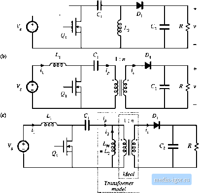 Fig. 6.37 Obtaining isokition in the SEPIC: (a) basic nonisolated conveiter, (b) isolated SEPIC, (e) with transformer equivalent circuit modef |