
|
| |
Строительный блокнот Introduction to electronics 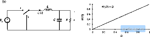 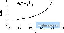 J ----- I 5 L 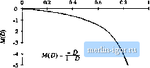 Fig. 2.5 Tliiee basic converlers iind ihcir dc tonveraion ratios M(D) = VIV: (a) buck, (b) boost, (c) buck-boosi. Fig, 2.6 Buck coiivciter circuit, wilh the inductor voltage Vjil) and capacitor current iJ(,t) waveforms specificsiiiy idcnti-fieci. -ТППП- + vU) - poneilt rij,j(0 arising from the incomplete isttemiation of the switching harmonics by the low-pass filter. The magnitude of v,p j,(f)has been exaggerated in Fig. 2.7. The output voltage switching ripple should be small in any well-designed converter, since the object is to produce a dc output. For example, in a computer power supply having a 3.3 V output, ihe switching ripple is normally required to be less than a few tens of millivolts, or less than 1% of the dc component V. So it is nearly always a gt>od approximation to assume that the magnitude of the switching 2.2 hiducior Voh-Secwd Balance, Capacitor Charge Bakmce. andihe SmaU-Rippk Approximaiim\ Fig. 1.7 Output vokage waveform v{t), ton.sistiiig of dc comininent V and swiictiiiig ripple v, ,J-l)- v(l) Actual waveform dc component V ripple is mutli smaller than the dt component: Therefore, the output voltage v(f) is well approximated by its dc component V, with the small tipple term iri,.,) neglected: v(0 = V (2.6) Tills approximation, known а.ч the sraall-ripple approximation, or the lineiu-ripple approximation, greatly simplifies the analysis of the converter waveforms and is used throughout this book. Next let us analyze the inductor current waveform. We can find the inductor current by integrating the inductor voltage waveform. With the switch in position 1, the left side of the inductor is connected to the input voltage V, and the circuit reduces to Fig. 2.8(a). The inductor voltage 1,(0 is then given by (2.7) As described above, the output voltage ij(0 consists of the dc component F, plus a small ac ripple term v-,jj)J.t). We can make the small ripple approximation here, Eq. (2.6), to replace ij(?) with its dc component V\ (2.S) So with the switch m position 1, the inductor voltage is essentially constant and equal \.aV~V, as shown in Fig. 2.9. By knowledge of the inductor voltage waveform, the inductor current can be found by use of the definition 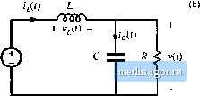 (3.9) + MO - a < v(x) Fig. 2,8 Buck auwmer circuit: (a) while the switch is in position 1, (h) wiiile tlia switch is i[i positioa 2. Fig. 2,9 ,Slejdy-K(iilt; imlucinr viiliajjc wavtirorni, buirkcuiivetler, Switch position: Thus, during the first interval, when i,(f) is approximately (l*, - V), the .slope of the inductor eurreni waveform is il!,{l) V,(0 dt - L (2. ID) which follows by dividing Eq. (1.9) by L, and substituting Eq. (2.8). Since the inciuetor voltage v,(l) i.s essentially constant while the switch is in position 1, the inductor current slope is also essentially constant and the inductor current increa.ses linearly. Similar arguments apply during the second .subinterval, when the switch is in position 2. The left side of the inductor is then connected to ground, leading to ihe circuit of Fig, 2,8(b). It is important to consistenlly define the polarities of the inductor current and voltage; in particular, the polarity of i,(f) is defined consistently in Figs. 2.7, 2.8(a), and 2.S(b). So the inductor voltage during the second .subinterval is given by Use of the small ripple approximiition, Eq. (2.6), leads to (2.11) (2.12) So the inductor voltage is also essentially constant while the switch is in position 2, as illustrated in Fig. 2.9. Substitution of Eq. (2.12) into Etj. (2.9) and solution for the slope of the inductor current yields V L (2.13) Hence, during the .second subinterval the inductor current changes with a negative and essentially constant slope. We can now sketch the inductor current waveform (Fig. 2.10). The inductor current begins at some initial value /,(0). During the first .subinterval, with the .switch in position 1, the inductor current increases with the slope given in Eq. (2.10). At time = >Гл the switch changes to position 2. The current then decreases with the constant slope given by Eq. (2.13). At time t- 7j, the switch changes back to Fig. 2.10 Sioady-bLEitt; induLUH- cunetu waveform, I tmck ioiivcrtcr. 1(0) 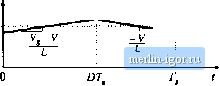 |