 | |
|
Строительный блокнот Introduction to electronics Fig. 7,32 Bucfc-bonst totivertcr drcuit: (я) during subiiiterval J, (b) during subinterval 2, d\(t) dt y(f)
(7,:2C) So we have identified the state equation matrice.s A B Сц and E,. With the switch in position 2, the converter circuit of Fig. 7.32(b) is obtained. Forthis subinterval, the inductor voltage, capacitor current, and converter input current are given by dl R i,it) = 0 When written in state-space form, these equations become (7.121) 0 1 dm dt A; [00]
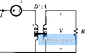
(7.122) The next step is to evaluate the state-space averaged equilibriutn equations (7.У2) to (7.94). The aveiaged tnatrix A is a = dai +t>aj = d In asirailar manner, the averaged matrices B, C, and E are evaluated, vi-ith the follovi-ing results: - OR ., D (7.123) В = OB J -i- /TBj = с = C-C, + OCj = The dc state equations (7,92) therefore become -Off D 7j = U>0 D -1У 0 0 D -D 0 0 (7.124) (7.125) Evaluation ofEq. (7.95) leads to the follovifing solution for the equilibrium state and output vectors: D 1 d-/f DR D ff-R DR (7.126) ff R Alternatively, the steady-state equivalent circuit of Fig. 7.33 can be constructed as usual from 7.3 Stale-SpiiceAveraging 1 : D I-W- Ф II  Fig. 7J3 Dc circiiii model for the buck-boost converter example, equivalent to Eq. (7.125), Eq, (7,125). The top row of Eq. (7.125) could have been obtained by application of the principle of inductor volt-second balance to the inductor voltage waveform. The second row of Eq. (7.125) could have been obtained by application of the principle of capacitor charge balance to the capacitor current waveform. The i,(0 equation expresses the dc component ofthe converter input current. By reconstructing circuits that are equivalent to these three equations, the dc model of Fig. 7.33 is obtained. The small-signal mtxiel is found by evaluation of Eq. (7.95). The vector coefficients of /(/) in Eq. (7.95) are (a,-a,)x + (b,-Bj]u = (c,-Cj)x + (e,-f ]u = [;J The small-signal ac state equations (7.95) therefore become
D 1
dif) + 00 VjtO 0 (7.128) Note that, smce the diode forward voltage drop is modeled as the constant value Уд, there are no ac variations iti this soiuce, aiid vit) equals zero. Again, a circuit model equivalent to Eq. (7.128) can be constructed, in the usual manner. When written in scalar form, Eq. (7.126) becomes 1Ш = [У vU) - D tit) + D v(f) + [ V, - V - ;, , + Vj rf(0 C = -DHt)-Mit) Lit)D>(t) + ld\l) (7.129) Circuits corresponding to these equations arc listed in Fig. 7.34. These circuits can be combined into the complete small-signal ac equivalent circuit model of Fig. 7.35. |
|||||||||||||||||||||||||||||||||||||||||||||||||||||||||||||||||||||||||||||||||||||||||||||