
|
| |
|
Строительный блокнот Introduction to electronics 7.4 J Perturbation and Linearization The model of Fig. 7.39(c) is nonlinear, because the dependent generators given by Eqs. (7.136) and (7.137) are nonlinear functions of d(t), {iiit)), and Toconstruct a small-signal ac model, we per- turb and linearize Eqs. (7.136) and (7.137) in the usual fashion. Let rf(/) = D-K/(/) {;i(/)}j. =/,+ri(() (7.13S) (7.139) With these substitutions, Eq. (7.136) becomes It is desired to solve for the dependent quantity V, + v. Equation (7.139) can be manipulated as follows: The terms (7(f)i3(() and £Г(/)0(0 are nonlinear, and are small in magnitude provided that the ac variations are much smaller than the quiescent values [as in Eq. (7.32)]. When the small-signal assumption is satisfied, these terms can be neglected. Upon eliminating the nonlinear terms and solving for the switch network dependent output + Vj, we obtain (7.141) The term iV,/DD)J(t) is driven by the control input d, and hence can be represented by an independent voltage source as in Fig. 7.40. The temi (DlDXV + VjW) is equal to the constant value (D/D) niidtiplied by the port 2 independent voltage (V2+ vU)}. This term is represented by a dependent voltage source in Fig. 7.40. This dependent source will become the primary winding of an ideal transformer. In a similar manner, substitution of the relationships (7.138) into Eq. (7.137) leads to: Fig. 7.40 Linearization of the dependent voltage source. (0 + 4/, + ,%) = [D-J)(/, + r*,) (7.142) The terms i, (Ыа) and titit) are nonlinear, and can be neglected when the small-signal assumption is satisfied. Elimination of the nonlinear terms, and solution for/ -I- Г, yields: (7.143) 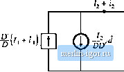 Fig. 7.41 Liriearizaiioi! of [he dependent currcnl source. The term (/j/DD)({t) is driven by the control inptit d(t), and is represented by an independent current source in Fig. 7.41. The term (DlDXi + (0) is dependent on the port 1 current (/ + t(()). This term is modeled by a dependent current source in Fig. 7.41; this source will become the secondary winding of an ideal transformer. Equations (7,141) and (7.143) describe the averaged switch network model of Fig. 7.39(d). Note that the model contains both dc and small-signal ac terms: one equivalent circuit is used for both the dc and the small-signal ac models. The transformer symbol ctm-tains both a solid line (indicating that it is an ideal transformer capable of passing dc voltages and currents) and a sinusoidal line (which indicates that small-signal ac variations are modeled). The averaged switch model of Fig. 7.39(d) reveals that the switch network performs the functions of: (i) transformation of dc and small-signal ac voltage and current levels according to the D:D conversion ratio, and (ii) introduction of ac voltage and current variations into the convertercircuit, driven by the control input d{t). When this model is inserted into Fig. 7.37, the dc and small-signal ac SEPIC model of Fig. 7.42 is obtained. This model can now be solved to determine the steady-state voltages and currents as well as the small-signal convertertransfer functions. The switch network of Fig. 7.39(a) can be identified in all two-switch converters, including buck, boost, SEPIC, Cuk, etc. As illustrated Fig. 7.43, a complete averaged circuit model ofthe converter can be constructed simply by replacing the switch network with the averaged switch model. For exam- D :D Fig. 7,42 A dc and i;mall-signal ae averaged circuit model of the CCM iJEPIC. Power inpttt Ttme-imariant network containing converter reactive eletnents -1ППГ v,(0 \ network vi(f) cycle Load R < v(0 Power input Time-invariant network containing converter reactive eletnents ТППР i i, + h : V, : 2 2 + Averaged switch network I dU) Duty cycle Load Fig. 7,43 С or к true I ion of lui avyraetl circuil model for a Iwo-swiLdi totwerrer орегл!! !; in CCM: (a) lite converter circuit willi (he general Iwu-swiitti [iclwurk identified; (b) dc and ac .smuli-sigiial averaged circuit model obtained by replacing tlie .switch iielwork with ihc average;*! rnndof |