
|
| |
|
Строительный блокнот Introduction to electronics Qj-£it)dt{i,) (2.27) The average value, or dt component, of the capacitor current must be zero in equilibrium. This should be an intuitive result. If a dc current is applied to a capacitor, then the capacitor will charge continually and its voltage will increase without bound. Likewise, if a dc voltage is applied to an inductor, then the flux will increase continually and the inductor current will increa.je without bound. Equation (2.27), called the principle of capacitor antp-sccond balance or capacitor charge balance, can be used to find the steady-state currents in a switching converter. BOOST CONVERTER EXAMPLE The boost converter. Fig. 2.13(a), is another well-known switched-mode converter that is capable of producing a dc output voltage greater in magnitude than the dc input voltage. A practical realization of the Switch, using a MOSFET and diode, is shown in Fig. 2.13(b). Let us apply the small-ripple approximation and the principles of inductor volt-second balance and capacitor charge balance to find the steady-state output voltage and inductor current for this converter. With the switch in position 1, the right-hand side of the inductor is connected to ground, resulting in the network of Fig. 2.l4(aJ. The inductor voltage and capacitor current for this subinterval are given by = v.. (2.28) Use of the linear ripple approximation, i = V; leads to .>(t) + v(l) - 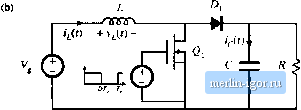 Fig. 2.13 Boost converter: (a) with ideal switch, (li) practiciil realisation using MOSFET and diode. 2.5 Bfw.tr Converter Example 23 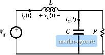 Fig. 2,14 Hoost convertei circuit, (a) wliile the switch ia iti posititm I, (h) while the switch i.4 ii) posiiioEi 2. (2.29) With the .switch in po.sition 2, the inductor is connected to the output, leading to the circuit of Fig. 2.14(b). The inductor voltage and capacitor current are then Use of the small-ripple approximation, v Vand = i, leads to (230) (2.31) Equations (2.29) and (2.31) are used to sketch the inductor voltage and capacitor current waveforms of Fig. 2.15. v,(f) Fiji. 2.15 BoOKL conveiter voltage and current wavcforins. - V/R I-V/R - DT - -ТППГ1- + v{0 - Hg. 2,16 Pt toiiversioii tatio M(l}) of tlic boost conveiler. It can be inferred from the inductor voltage waveform of Fig. 2.15(a) that the dc output voltage Vis greater than the input voltage V. During the first .subinterval, V/it) is equal to the dc input voltage V, and positive volt-seconds are applied to the inductor. Since, in steady-state, the total volt-seconds applied over one switching period must be zero, negative volt-secouds must be applied during the second sub-interval. Therefore, the inductor voltage during the secondsubinterval, (y y imist be negative. Hence, V is greater than V. The total volt-seconds applied to the inductor over one switching period are: (232) By equating this expression to zero and collecting terms, one obtains VJD + D)-VD- = Q Solution for V, and by noting that ф -i- D) = 1, yields the expression for the output voltage, (2.33) (2.34) The voltage conversion ratio МФ) is the ratio of the output to the input voltage of a dc-dc converter. Equation (2.34) predicts that the voltage conversion ratio is given by M(D) = f = = -L a \-D (2.35) This equation is plotted in Fig. 2.16. At D = 0, V.The output voltage increases as D increases, and in the ideal case tends to infinity as D tends to 1. So the ideal boost converter is capable {)f producing any output voltage greater than the input voltage. There are, of course, limits to the output voltage that can be produced by a practical boo.4t converter. In the next chapter, component nonidealities are modeled, and it is found that the inaxinium output voltage of a practical boost converter is indeed limited. Nonetheless, very large output voltages can be produced if the nonidealities are .sufficiently small. Tlie dc component of the inductor current is derived by use of the principle of capacitor charge balance. During the first subinterval, the capacitor supplies the load current, and the capacitor is partially discharged. During the second subinterval, the inductor current supplies the load and, additionally, recharges the capacitor. The net change in capacitor charge over one switching period is found by integrating the i(i,t) waveform of Fig. 2.15(b), |