
|
| |
|
Строительный блокнот Introduction to electronics Fig. 7.58((]). This model predicts that the small-signal control-to-out:put transfer function is (7Л67) This transfer function is found hy setting the 0(s) variations to zero, and solving for the dependence of C(i) on c?(j). Figure 7.5S(d) is the complete canonical circuit, which can model any PWM CCM dc-dc converter. 7J.2 Example: ManipulatJon of the Buck-Boost Converter Model into Cimonical Form To illustrate the steps in the derivation of the canonical circuit model, let us manipulate the equivalent circuit of the btick-boost converter into canonical form. A small-signal ac equivalent circuit for the buck-boost converter is derived in Section 7.2. The result, Fig. 7.16(b), is reproduced in Fig. 7.59. To manipulate this network into canonical form, it is necessary to push all of the independent d{T) generators to the left, while pushing the inductor to the right and combining the transformers, The (,V - V)d(l) voltage source is in series with the inductor, and hence the positions of these two elements can be interchanged. In Fig. 7.60(a), the voltage source is placed on the primary side of the l.-Dideal transformer; this requires dividing by the effective turns ratioD. The otitput-side/<f(0 current source has also been moved to the primary side of the /):[ transformer. This requires mtiltiplyingby the turns ratio l/D, The polarity is also reversed, in accordance with the polarities of the D.\ transformer windings. Next, we need to move the ld{tyD current source to the left of the inductor. This can be done using the artifice illustrated in Fig. 7.60(b). The ground connection of the current source is broken, and the source is connected to node Л instead. A second, identical, current sotirce is connected from node A to ground. The second source causes the current flowing into node A to be unchanged, such that the node equations of Figs. 7.60(a) and 7.60(b) are identical. In Fig. 7.60(c), the parallel combination of the inductor and current source is converted into Thevenin equivalent form. The series combination of an inductor and voltage source are obtained. In Fig. 7.60(d), the ldit)/U current source is pushed to the primary .side of the V.D transfortner. The magnitude of the current sotirce is multiplied by the turns ratio D. In addition, the current source is pushed through the (V, - V)dityD voltage source, using the previously described artifice. The ground connection of the source is moved to node S, and an identical source is connected from node В to ground such that the circuit node equations are unchanged. 1 : D GD: 1 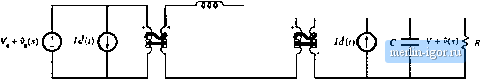 Fig. 7.59 Small-signal ac model of tbe buck-boost converter, before nianipubiiott into canonical form. V.-V 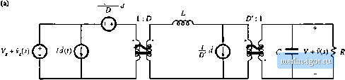 T f 1 T ж f 1 V.-V St/ J с ±Z VtU)k R 1:D л D:l тллр Fig. 7.60 Steps in the tiianipulation of the buck-boost ac inodel into canonical form. 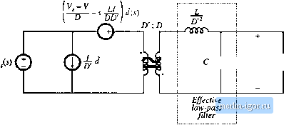 ZZ. V + v(i) < R Fig. 7.61 Ttie buck-boost conveiter nunlel, in canonical lorm. Figure 7.6] is the final form of the model. The iniiuctor is moveti to the seconiiary side of the D: 1 transfonner, by multiplying by the square of the turns ratio as shown. The sLl3(tyD voltage source is moved to the primary side of the 1 :Z) transformer, by dividing by the turns ratio D. The voltage and current sources are combined as shown, and the two transformers are combined intt) a single D.D transformer. The circuit is now in canonical form. It can be seen that the inductance of the effective lt)w-pass filter is not simply equal to the physical inductor value L, but rather is equal to LID. At different quiescent operating points, with different values of D, the value of the effective indtictance will change. In ct)nseqtience, the transfer function, input impedance, and output impedance of the effective k)W-pass filter will also vary with quiescent operating point. The reason for this variation is the transformation of the inductance value by the effective D:i transformer, It can also be seen from Fig. 7,fil that the coefficient of the (/() vohage generator is ft,lj (7.168) This expression can be simplified by substitution of the dc relationships (7.29). The result is (7.169) When we pushed the output-side /<f(l) ctirrent source thrt)ugh the inductor, we obtained a voltage source having a frequency dependence. In consequence, the e(,v)rf voltage generator is frequency-dependent. 7.S.3 Canonical Circuit Parameter Values for Some Common Converters For ideal CCM PWM dc-dc converters containing a single inducttff and capacittjr, the effective low-pass filter of the canonical model should contain a single inductor and a single capacitor The canonical model then redtices to the circuit of Fig. 7.62. It is assumed that the capacitor is connected directly across the load. The parameter values for the basic buck, boost, and buck-boost converters are ctjllected in Table 7.1. Again, it should be pointed out that the effective inductance depends not only on the physical |