
|
| |
Строительный блокнот Introduction to electronics 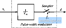 Fig. 7.й( A more iiccuruta pulse-wkith muduliiLor inodel, including sainpling. SUMMARY OF KEY POINTS 1. The CCM converter iinalylical [echniques of Chapters: 2 iind 3 can be extended U) predict converter ac behavior. The key step is lo average the converter waveforms over one switching period. This removes the swilching harmonics, thereby e?:pt)sing directly the desired dc und low-frequency ac components of the waveforms. In parucLilar, expressions for the averaged inductor voltages, capacitor currenl.s. and converter input current are usually found. 2. Since switching converters are nonlinear systems, it is desirable to consLrLicL small-signjil linearized models. This is accomplished by perturbing and linearizing the averaged model about a tjuiescent operating poinL, 3. Ac equivalent circuits can be constructed, in the same manner used in Chapter 3 to construct dc equivalent circuits. If desired, the ac ecjLiivalenl circLiils may be relined to account for the effects of converter losses and other nonidealities. 4. The state-space averaging method of Section 7.3 is essentially the same as the basic approach of Section 7,2, except that the formality of the sliite-space network description is used. The general results are listed in Section 7.3.2. 5. The circuit averaging technique also yields equivalent results, but the derivation involves manipulation of circuits rather than equations. Switching elements are replaced by dependent voltage and current sources, whose waveforms are defined Iti be identical lo the swilcli waveforms of the actiial с ire ail. This leads to a circuit having a time-in variant topology. The waveforms are then averaged to remove the switching ripple, and perlLirbed and linearized about a cjuieseent operating point lo obtain a small-signal model. 6. When the switches are lhe only time-varying elements in the converter, then circuit averaging affects only lhe swiich network. The converter model can then be derived by simply replacing lhe swiich network with its averaged mtjdel. Dc and small-signal ac models of several common CCM switch networks are listed in Secdtm 7.4.4. Conduction and swilching losses can also be modeled using this approach. 7. The canonical circuit describes the basic properties shared by all dc-dc PWM converters operating in the continuoLLs conduction mode. Al the heart t)l the model is the ideal 1:M{D) transformer, iniroduced in Chapter 3 to represent the basic dc-dc conversion function, and generalized here to include ac variations. The converter reacdve elements introduce an eflecdve low-pass filler into ilie network, The model also includes independent sources thai represent the effect of duty cycle variations. The parameter values in the canonical models of several basic converters are tabulated for easy reference. S, The conventional pulse-width modulator circuit has linear gain, dependent on the slope of the sawtooth waveform, or ecjLiivalently on its peak-to-peak magnitude, Refeeiences [1] R. D. MiDDLbEROOK and Slobodan Cuk, A General Unified Approacfi lo Modeling Switching-Converter Power Stages, Internatiomil Journal of Electronks, Vol. 42, No. 6, pp. 521-550, June 1977. [2] Slobodan Cuk, Modeling, Analysis, and Design of Switching Converters, Ph.D. thesis, California Inshtute of Technology, November 1976. [3] R. D. MiDDLEBROOK and slobodan С(Ж, Modeling and Analysis Methods for Dc-to-Dc Switching Converters, Proceedings ofthe IEEE Intcnwiiorwl Semiconductor Power Converter Conference, 1977 Reconl, pp. 90-1II, March 1977. Reprinted in Advances in Switched-Mode Power Conversion. Vol. 1, Irvine: Teslaco, 1983. [4] G. W. Wester and R. D. Middlebrook, Low-Frequency Characterization of Switched Dc-Dc Convert-eni, IEEE Transactions an Aerospace and Electronic Systems, Vol. AES-9, pp. 376-3S5, May 1973. [5] Daniel M. Mitchell, Dc-Dc Switching Regnkitor Analysis. New York: McGraw-Hill, 1988, [6] Seth R. Samders and Georue C. Veroese, Synthesis of Averaged Circuit Models for Switched Power Converters, IEEE Transactions on Circuits andSy.items, Vol. 38, No, 8, pp. 905-915, August 199J. [7] P. T. Krein, j. BEhfTSMAN, R. M. Ba.ss, and B. C. LEStEUTRE, On the Use of Averaging for the Analysis of Power Electronic Systems, IEEE Transaction.; on Power Electronic.;, Vol, 5, No. 2, pp. 182-190, April 1990. L*J b, Lehman and R. M. Bass, Switching Frequency Dependent Averaged Models for PWM DC-DC Converters, IEEE Transactions on Power Electronics, Vol, 11, No. 1, pp. S9-98, January 1996. [9J R. M. Bass and J. Sun, Averaging Under Large-Ripple Conditions, IEEE Power Electronics Specialists Conference, 1998 Record, pp. 630-632, May 1998. [10] Arthi.r R, BKtJWK and R. D. Middlebrook, Sampled-Data Modeling of Switching Regulators, IEEE Power Electronics Specialists Conference, 1981 Record, pp. 349-369, June 1981. [llj R. D. MiDDLEBRtMK, Predicting Modulator Phase Lag in PWM Converter Feedback Loops, Proceedings of tlie Eifrlith National Solid-State Power Conversion Conference (Powercon 8), Apnl 1981. 112J A. KiSLOVSKi, R. Redl, and N. Sokal, Dynamic Analysis of Swiichin-Mode DC/DC Conveyters, New York: Van NoslrandReinhold, 1994 [13] R. Tymerski and V. Vorperian, Generadon, Classilicaiion and Analysis of Switched-Mode DC-to-DC Converters by the Use of Converter Cells, Proceedings of the J9S6 International Teiecomnnmications Energy Conference (INTELEC86), pp. ISl-195, October 1986. [14] V. Vorperian, R. lYMERSKt, and F. C. Lee, Equivalent Circuit Models for Resonatit atid PWM Switches, IEEE Transactions on Power Electronics. Vol. 4, No. 2, pp. 205-214, April 1989, [15] V. VoRPEEiAS, Simplified Analysis of PWM Converters Using the Model of the PWM Switch: Parts 1 and 11, IEEE Traiuactions on Aerospace anil Electronic Systems, Vol. AES-26, pp. 490-505, May 1990. [16] S. Freeland and R. D. Middlebrck:k, A Unified Analysis of Converters with Resonant Switches, IEEE Poiver Electronics Specicilist.s Conference, 19S7 Record, pp. 20-30. [17] Arthlr WmxsKi and Robert Ericksok, Extension of State-Space Averaging to Resonant Switches -iind BevonJ, IEEE Tiausaciwns on Power Electronics. Vof 5, No, 1, pp. 98-109, Itmuiiry 1990. [18] D. M.-KSLMOvic and S. CtJK, A Unified Analysi.s of PWM Converters in Discontinuous MikIcs, IEEE Tran.sactions on Power Electronics. Vol. 6, No. 3, pp. 47690, Iul> 1991. [19] D. I. Shortt and F. C. Let;, Extensions of the Discrete-Average Models for Convener Power Stages, IEEE Power Electronics Specialists Conference. 1983 Record, pp. 23-37, lune 1983. [20] O. Al-N.seem and R.W. Erickson, Prediction of Switching Loss Variations by Averaged Switch Modeling, IEEE Applied Power Electronics Conference. 2000 Record, pp. 242-248, February 2000. Problems 7.1 An ideal boost converter operates itt die continuous conduction mode. (a) Deleimine the nonlinear averaged equations of this converter. (b) Now construct a small-signal ac model. Let d{t)D-r{l) {1(0).1 +lit) (v(l))j. = V + v(0 where lii*, f, and Vare steady-state dc values; and d{t) are small ac variations in the power and control inputs, and and v() ;ае the resulting small ac variations in the inductor current and oulpui voltage, re.spectively, Show thai lhe following model results; Large-signal dc components 0 = - DV + 0 = Ш--К Small-signal ac components c=mii)!dm--f 7.2 Construct an equivalent circuit that corresponds to the boost converter small-stgrral ac equations derived in Problem 7.1(b). 7.3 Manipulate your boost converlerequivalent circuit оГРгоЫеш 7.2 into canonical form. Explain each sitep in your derivation. Verify that the elements in your canonical model agree with Table 7.1. 7.4 The ideal current-fed bridge converter uf Fig. 2.31 operates in lhe continuous conduction mode. (a) Determine the nonlinear averaged equations of this converter, (b) Perturb and linearize these equations, to determine the small-signal ac equations of the converter. |