 | |
|
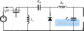
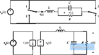
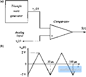
Строительный блокнот Introduction to electronics РтЫеш v/f)  Fig. 7,fi7 Inverse SEPIC, Problem 7.7. (c> Construct a smiill-signal ac equivalent eircuit model for this converter. 7.5 Construct J ctjmplete small-signtil tic ecuivjlent circtiii mtjdel ftjr the flyback converter shown in Fig. 7.1 S, operating in contimtous conduction mode. The transformer contains magnetizing Indnctance L referred to the primary. In addition, the transformer exhibits .significiini core loss, which can be modeled by a resistor/?;, in parallel with the primary winding. All otherelements щ-е ideal. You may use any valid mediod to solve this problem. Yotn model should correctly predict variations in iU). 7,fi Modeling the Cut convener. Yon may use any valid method lo solve ihis problem. (a) Derive the small-signal dynamic equations that model the ideal Cllk converter. (b) Construct a complete small-signal equivalent circuit model Itir the Cuk converter. 7.7 Modeling the inverse-SEPIC. You may use iiny valid method tu solve this problem. (a) Derive the small-signjil dynamic equjtions ihai mtidel the ctmverler shown in Fig. 7.Й7. h) Construct ;i complele smtill-signal equivalent circuit model for the inverse-SEPIC. 7.8 Consider the nonideal buck convener of Fig. 7.68. The input voltage source v(t) has internal resistance R. Other component nonidealities may be neglected, (a) Using the state-space averaging methtKl, determine the sinall-signal nc equations that describe variations in r, and i, which occur owing lo vjiriations in the transistor duly cycle dand input vohage v, (b) Ctinslruct an ac equivalent circuit model corresponding to ytjur eqiutions of pjirt (гг). (c) Stiive ytiur model lu determine an expressitin fur the smjli-signai ctmlrtil-Ui-titLlptil transfer luncuon.  FIk- 7.fi8 Motiideal buck converter. Problem 7,8. 7.9 Use Ihe circtiit-averaging technique lo derive the dc and small-signal ac equivalent circuit ofthe buck converter with input filler, illustrated in Fig. 2.32. All elements are ideal. <b)  Fig. 7.69 Bridge inverter. Problem 7.11: (a) circuit, (b) large-signal averaged model. 7.10 A flyback converter operates in the continuous conduction mode. The MOSFET switch has on-resistance й , and the secondary-side diode has a constant forward voltage drop Vq. The flyback transformer has primary winding resistance and secondary winding resistance fi,. (a) Derive the small-signal nc equations for this converter. (b) Derive a complete small-signal ac equivalent circuit model, which is valid in the continuous conduction mode and which correctly models the above losses, as well as the converter input and output ports. 7.11 Circuit averaging of the bridge inverter circuit of Fig. 7.69(a). (a) Show that the converter of Fig. 7.69(a) can be written in the electrically identical form shown in Fig. 7.69(b). Sketch the waveforms i,it) and (l). (b) Use the circuit-averaging method to derive a large-signal averaged model for this converter. (c) Perturb and linearize your circuit model of part (b), to obtain a single equivalent circuit that models dc and small-signi! ac signals in the bridge inverter. 7J2 Use the circtiit averaging method to derive an equivalent circuit that models dc and small-signal ac sig- nals in the buck-boost converter. You may assume that the converter operates in the continuous conduction mode, and that all elements are ideal. (a) Give a time-invariant electrically identical circuit, in which the switching elements are replaced by equivalent voltage and current sources. Define the waveforms of the sources. (b) Derive a large-signal averaged model for this converter (c) Perturb and linearize your circuit model of part (b), to obtain a single equivalent circuit that models dc and small-signal ac signals in the buck-boost converter, 7J3 The two-output flyback converter of Fig. 7.70(a) operates in the continuous conduction mode. It may be assumed that the converter is lossless. (a) Detive a small-signal ac equivalent circuit for this converter. (b) Show that the small-signal ac equivalent circuit for this two-output converter can be written in the generalized canonical form of Fig. 7.70(h). Give analytical expressions for the generators £>(.!) andy(s). 7.14 A pulse-width modulator circuit is constructed in which the sawtooth-wave generator is replaced hy a triangle-wave generator, as illustrated in Fig. 7.71(a). The triangle waveform is illustrated in Fig. 7.71(b). emblems 261 Fig. 7.70 T\vo-output tlyback converter, Problem 7.13; (a) converter circuit, (b) small-signal ac equivalent circuit. Fig. 7.71 Piilse-width modulator, Problem 7.14.  PWM yvaveform |